Component Diagrams
Now you can illustrate the physical structure of the code easily in UModel using component diagrams.
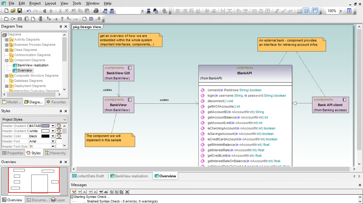
Component diagrams mapping the logical view of the project classes to the actual files containing the source code where the logic is implemented. When UModel generates code, the component diagrams represent the location of the Java or C# source code files for your classes. When reverse engineering an existing project, the component diagrams can help you correlate each UModel class diagram with the source code files.
The UModel component diagram toolbar includes realization arrows, which assign each class to a component, and other elements you’ll want when drawing component diagrams. UModel makes it easy to create a new component from either the toolbar or a context-sensitive right-click menu. Then you can copy and paste project classes from your class diagrams or drag them from the model tree window, and assign classes to a component by drawing realization arrows.
You’ll specify the directory for the source code corresponding to your model in the component diagram properties window. This is where you tell UModel to store generated code, and also where you tell it to find code to use for reverse engineering.


