Charts
Charts in the SPS provide a graphical representation of data in the source XML document. In an SPS design that uses XSLT 2.0 or 3.0, a chart is set up by specifying a sequence of items for each axis of the chart. StyleVision then automatically generates the chart in the various output formats.
The table below shows the types of charts that can be created in an SPS design and the kind of data items that are required for each of the chart's axes. The dataset to be used for each axis is specified separately with an XPath expression.
Chart type | X-Axis | Y-Axis | Number of Series (on Z-Axis) |
Pie Charts (2D, 3D) | Text | Numeric | 1 |
Bar Charts Ungrouped (2D, 3D) | Text | Numeric | 1 |
Bar Charts Grouped (2D, 3D) | Text | Numeric | > 1 |
Category Line Graphs | Text | Numeric | 1 line = 1 series |
Value Line Graphs | Numeric | Numeric | 1 line = 1 series |
Area and Stacked Area Charts | Text | Numeric | 1 area = 1 series |
Candlestick Charts | Text | Numeric | 3 or 4 |
Gauge | — | Numeric | 1 |
Overlay Charts | Text | Numeric | = 1 or > 1 per chart |
| Note: | Pie charts and gauge charts have a single nominal series, which requires no name. So if a series name is entered in the data selection, it is ignored. For ungrouped bar charts, however, the name of the single series, if present, is used for the legend. For gauge charts, in addition to any Series Name entry being ignored, the X-Axis data selection is also ignored; only the Y-Axis selection is used for gauge charts. |
| Note: | Charts are not rendered in Text output. |
Inserting a Chart
The XML Schema node within which a chart is created in the design will be the context node of the XPath expressions to select the chart's axes and other chart data. A chart must therefore be inserted within a suitable context node: one from which correct XPath expressions to select the required data can easily be constructed.
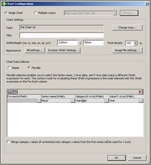
To insert a chart, right-click at the required location and select Insert Chart from the menu that pops up (or use the menu command Insert | Insert Chart). Alternatively, select the Insert Chart icon in the toolbar of StyleVision and then click in the design at the location where you wish to insert the chart. These insertion methods pop up the Chart Configuration dialog (screenshot below).
The Chart Configuration dialog has three parts:
•Single or Multiple layers: Multiple layers can be selected to create overlay charts, in which multiple charts can be presented, one overlaid upon the other in a sequence of layers.
•Chart Settings: To select the chart type and define the appearance of the chart
•Chart Data Selection: To select the data for the various axes of the chart using either the simple option or flexible option
On clicking OK in the Chart Configuration dialog, the chart is inserted in the design.
Editing chart settings and data selection
If you wish to change chart settings or a chart's data selection after a chart has been created, right-click the chart in the design and select Edit Chart Settings. This pops up the Chart Configuration dialog (screenshot above) of that chart. You can edit the chart's settings or data selection in the dialog, then click OK to finish.
