Example: Create and Generate an XML Schema
This example shows you how to model a new XML Schema with UModel, step by step. After modeling the schema visually using UML, you will generate the schema file. More specifically, you will learn how to create and generate the product.xsd schema listed below.
<?xml version="1.0" encoding="UTF-8"?> |
product.xsd
As shown above, the product.xsd schema has two namespace declarations:
1.The default XML Schema namespace http://www.w3.org/2001/XMLSchema mapped to the "xs" prefix.
2.The secondary namespace https://www.altova.com/umodel mapped to the "prod" prefix, which is also the target namespace.
Also, the XML schema has a global product element, a complex type ProductType and a simple type SizeType.
Declaring namespaces and file encoding
To proceed, create a new UModel project. Right-click the Root package, and select New Diagram | XML Schema Diagram from the context menu. When prompted to include the UModel XSD Profile, click OK.
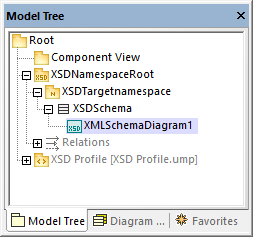
In the Model Tree Window, rename "XMLSchemaDiagram1" to "MainDiagram". This is the diagram where most schema components will be created, except for namespace declarations.
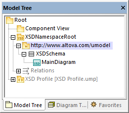
Next, rename "XSDTargetNamespace" to "https://www.altova.com/umodel" (recall that this is the required target namespace). This declares the target namespace of the new schema.
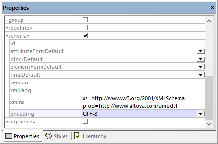
The two "xmlns" namespaces and the UTF-8 encoding can be set as follows:
1.Select the XSDSchema schema in the Model Tree.
2.In the Properties window, right-click the xmlns property and select Add Tagged Value | xlmns.
3.Edit the xmlns and encoding properties as shown below.
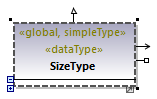
Optionally, you can quickly generate a new XML Schema diagram at namespace level that presents the same information visually, as follows:
1.In the Model Tree, right-click the namespace "https://www.altova.com/umodel" and select New Diagram | XML Schema diagram from the context menu.
2.When a message box with the following text appears: "Do you want to add the 'XML Schema Diagram' to a new 'XSD Schema'?", click No.
3.Drag the XML Schema from the Model Tree into the diagram.
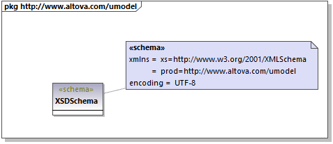
As shown above, the namespace and encoding are stored as Tagged Values and can be edited from the diagram window as well.
Add a simple type
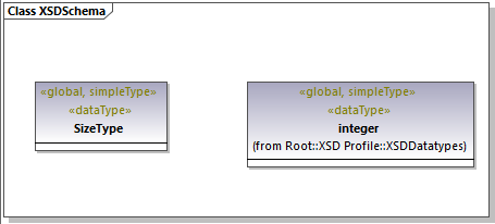
The following steps create the SizeType simple type to the XML schema. This is a type that restricts the base xs:integer type; therefore, we will add the base type to the diagram as well, and create a restriction relationship.
1.Double-click the MainDiagram in the Model Tree to open it.
2.Click the XSD Simple Type ![]() toolbar button, and then click inside the diagram.
toolbar button, and then click inside the diagram.
3.Rename the newly added simple type to SizeType.
4.Click inside the Model Tree and press Ctrl+F. The Find dialog box appears. Start typing "integer" and locate the integer type from the "XSDDataTypes" package of the "XSD Profile".
5.Drag the integer type into the diagram.
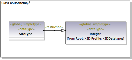
6.Click the Restriction ![]() toolbar button and drag the cursor from SizeType to integer. This creates the restriction relationship; see also Creating Relationships.
toolbar button and drag the cursor from SizeType to integer. This creates the restriction relationship; see also Creating Relationships.
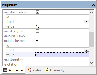
7.To define the minInclusive and maxInclusive values, select the simple type and edit the properties with the same name in the Properties window.
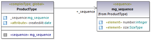
Add a complex type
The following steps add the ProductType complex type to the XML schema. All these steps take place in the MainDiagram as well.
1.Click the XSD Complex Type ![]() toolbar button, and then click inside the diagram.
toolbar button, and then click inside the diagram.
2.Rename the complex type to ProductType.
3.Right-click the complex type and select New | XSD Sequence from the context menu.
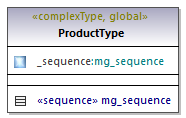
4.Drag the «sequence» class away from the complex type and into the diagram.
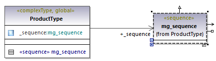
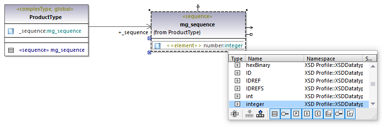
5.Right-click the sequence and select New | XSD Element (local).
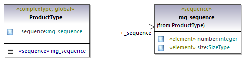
6.Change the element's name to number and set the type to integer. The integer type is a base XML Schema type from the XSD Profile. For instructions about setting an element's type, see Type Autocompletion in Classes.
7.Using the same steps as above, create the element size of type SizeType. Note that SizeType is the simple type created previously.
8.Right-click the complex type on the diagram and select New | XSD Attribute (local) from the context window.
9.Change the attribute's name to createdAt and the type to date.
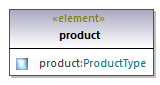
Add an element
Now that all the required types of the schema have been defined, you can add a product element of type ProductType, as follows:
1.Click the XSD Element (global) ![]() toolbar button, and then click inside the diagram. Notice that a class with the «element» stereotype and a single property is added.
toolbar button, and then click inside the diagram. Notice that a class with the «element» stereotype and a single property is added.
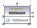
2.Rename the property to product and change its type to ProductType.
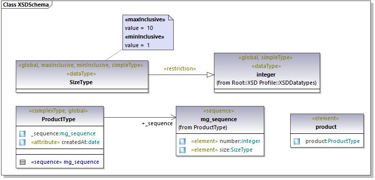
Completed design
The steps above conclude the design part of the schema. By now, your full schema design should look as follows:
Enable code engineering
To make it possible to generate a schema file from the model, let's now add a code engineering component that provides the schema generation details. The code engineering component is similar to other UModel project kinds, see also Adding a Code Engineering Component.
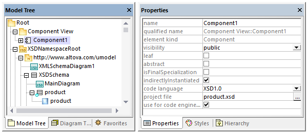
Right-click the "Component View" package in the Model Tree and add a new element of type Component. Make sure to change the component's properties as shown below:
1.The use for code engineering property must be enabled.
2.The code language property of the code engineering component must be set to "XSD 1.0".
3.The project file property of the code engineering component must point to the schema file that is to be generated (in this example, product.xsd).
Note: If a project file property is missing, enter product.xsd in the directory property and press Enter. A message box should now appear asking you to refer to a project file instead. Click Yes to confirm.
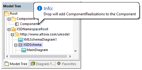
Finally, the XML Schema must be realized by the code engineering component, as described in Adding a Code Engineering Component. For the scope of this example, the quickest way to create the ComponentRealization relationship is as follows:
•In the Model Tree, drag the XSDSchema schema over the code engineering component (Component1) and drop it when a tooltip appears such as the one below:
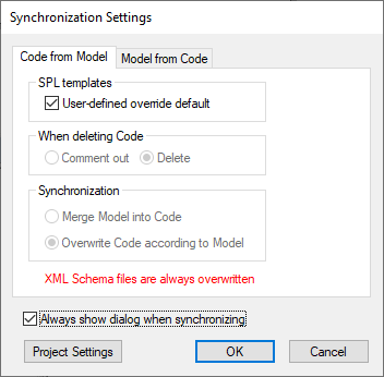
You can now generate the schema file. To do this, either press F12 or select the Project | Overwrite Program Code from UModel project menu command. Note that merging is not supported in case of XML Schemas; therefore, the dialog box shows a message in red to state this fact.
The new XML schema will be generated in the same folder as your UModel project.