Composite states
This type of state contains a second compartment comprised of a single region. Any number of states may be placed within this region.
To add a region to a composite state:
•Right-click the composite state and select New | Region from the context menu. A new region is added to the state. Regions are divided by dashed lines.
To delete a region:
•Click the region you want to delete in the composite state and press the Del key.
Deleting a region of an orthogonal state reverts it back to a composite state; deleting the last region of a composite state changes it back to a simple state.
To place a state within a composite state:
•Click the state element you want to insert (e.g. Logging in User), and drop it into the region compartment of the composite state.
The region compartment is highlighted when you can drop the element. The inserted element is now part of the region, and appears as a child element of the region in the Model Tree pane.
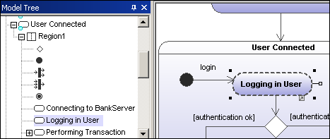
Moving the composite state moves all contained states along with it.
 Orthogonal state
This type of state contains a second compartment comprised of two or more regions, where the separate regions indicate concurrency.
Right clicking a state and selecting New | Region allows you add new regions.
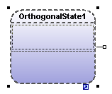
To show/hide region names:
•Click the Styles tab, scroll to the "Show region names on states" entry, and select true/false.
This state is used to hide details of a state machine. This state does not have any regions but is associated to a separate state machine.
To define a submachine state:
1.Having selected a state, click the submachine combo box in the Properties tab. A list containing the currently defined state machines appears.
2.Select the state machine that you want this submachine to reference.
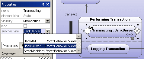
A hyperlink icon automatically appears in the submachine. Clicking it opens the referenced state machine, "BankServer" in this case.
To add entry / exit points to a submachine state:
•The state which the point is connected to, must itself reference a submachine State Machine (visible in the Properties tab).
•This submachine must contain one or more Entry and Exit points
1.Click the ConnectionPointReference icon ![]() in the title bar, then click the submachine state that you want to add the entry/exit point to.
in the title bar, then click the submachine state that you want to add the entry/exit point to.

2.Right-click in the Properties tab and select Add entry. Please note that another Entry, or Exit Point has to exist elsewhere in the diagram to enable this pop-up menu.
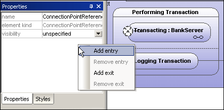
This adds an EntryPoint row to the Properties tab, and changes the appearance of the ConnectionPointReference element.
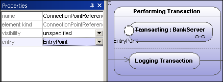
3.Use the same method to insert an ExitPoint, by selecting "Add exit" from the context menu.