Generating Diagrams
In addition to creating diagrams from scratch, you can also generate certain diagrams automatically from existing modeling elements or from program code. This topic shows you how to generate diagrams from existing modeling elements. For information about how to generate diagrams from source code, see:
•Generating Sequence Diagrams from Source Code
•Generating Package Diagrams While Importing Code or Binaries
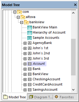
To generate diagrams from existing elements, right-click an element (for example, package) in the Model Tree, and then select Show in new diagram | <option> from the context menu. Below are some examples:
To create a diagram which shows the contents of an existing package:
•Right-click a package in the Model Tree window and select Show in new Diagram | Content from the context menu.
To create a diagram which shows the dependencies of an existing package:
•Right-click a package in the Model Tree window and select Show in new Diagram | Package dependencies from the context menu.
To create a diagram which shows the generalization hierarchy of a class:
1.In the Model Tree window, right-click a class which has generalization relationships to or from other classes (for example, class Account from the sample project C:\Users\<username>\Documents\Altova\UModel2025\UModelExamples\Bank_CSharp.ump).

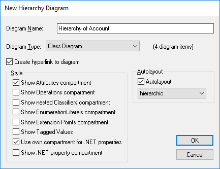
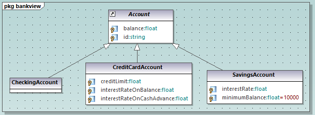
2.Select Show in new diagram | Generalization hierarchy from the context menu. A dialog box appears where you can adjust the preferences for the diagram to be created, including the diagram type. Notice the text "N diagram-items", which displays the number of items that are to be added to the diagram. In the example below, the chosen diagram type is "Class Diagram" and there will be four diagram items (classes) on the diagram: the Account class and three classes derived from it.

3.Click OK. The diagram is generated according to the selected options and opens in the Diagram window, for example:
