Modeling XML Schemas
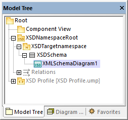
New XML Schema projects in UModel have the structure illustrated below. This structure is created automatically the first time when you add an XML Schema diagram to a new UModel project.

The "Root" and "Component View" packages are common to any UModel Project and cannot be deleted. "Root" is the topmost level under which any other packages are added, and "Component View" is used for code engineering (in this case, importing or generating schema files).
The "XSDNamespaceRoot" package includes all the namespaces used by your schema(s). To turn a package into an XSD Namespace Root, right-click it and select Code Engineering | Set as XSD Namespace Root from the context menu. If you import an existing XML schema into the project, this package is called "All schemas" by default.
The "XSDTargetnamespace" package is an XML Schema namespace. Multiple such namespaces may exist under the same XSD Namespace Root. To turn a package into a namespace, first select the package, and then select the «namespace» property (stereotype) in the Properties window.
"XSDSchema" is a schema, or, in UML terms, a class with the «schema» property (stereotype) selected in the Properties window.
XMLSchemaDiagram1 is the actual diagram that describes the schema's model. You can create XML Schema diagrams under an XSD Namespace Root, under an XML Schema Namespace, or under an XML Schema. In the example project illustrated above, the diagram is created under the XML schema.
The XSD Profile enables all the types and structures required to work with XML Schema in the project. If your project does not have this profile, you will be prompted to include it whenever you create a new XML Schema diagram. You can also add the XSD profile to a project explicitly, see Applying UModel Profiles.
Creating XML Schema diagrams
To create a new XML schema diagram:
1.Do one of the following:
a.Right-click a package in the Model Tree Window and select XML Schema Diagram from the context menu.
b.Right-click "Diagrams" or "XML Schema Diagrams" in the Diagram Tree Window and select New Diagram | XML Schema diagram from the context menu. A dialog box opens asking you to select the owner of the diagram. Select a package where the diagram should be stored, and click OK.
2.If the current UModel project does not include the XSD profile, a dialog box opens asking you to include it. Click OK to include the XSD profile into the current project, see also Applying UModel Profiles.
Adding new XML Schema elements
To add XML schema elements to a diagram:
•Click a specific toolbar button, and then click inside the XML Schema diagram.

To insert multiple elements of the same type, hold down the Ctrl key and click multiple times in the diagram.
As stated above, XML Schema diagrams can be created at various levels in the project's structure. If the diagram is at a level which does not allow placing a particular element, certain toolbar buttons are not meaningful and they show a tooltip with information instead of adding the element. |
The table below lists all the toolbar buttons and their purpose.
XSD Target Namespace | Adds an XSD target namespace. Clicking this button is meaningful if the diagram was created directly under an XSD Namespace Root. | |
XSD Schema | Adds an XML Schema Definition (XSD). Clicking this button is meaningful if the diagram was created under an XSD target namespace. | |
 | Element (global) | Adds a global element to the diagram. When you add an element, a property with the same name as the element is automatically generated in the attributes compartment. Set the property type to set the element's type. |
Group | Adds a named model group to the diagram. | |
 | Complex Type | Adds a global complex type to the diagram. In UML terms, this is a class that has the «global» and «complexType» stereotypes applied. |
Complex Type with Simple Content | Adds a global complex type with simple content. In UML terms, this is a data type that has the «global», «complexType», and «simpleContent» stereotypes applied. | |
 | Simple Type | Adds a global simple type. |
List | Adds a list type. | |
Union | Adds a union type. | |
Enumeration | Adds an enumeration. | |
Attribute | Adds an attribute. | |
Attribute group | Adds an attribute group. | |
Notation | Adds a notation type. | |
Import | Adds an import relationship. | |
Include | Adds an include relationship. | |
Redefine | Adds a redefine relationship. | |
 | Restriction | Adds a restriction relationship. |
Extension | Adds an extension relationship. | |
Substitution | Adds a substitution relationship. | |
Comment | Adds a comment. Comments are converted to annotations when you generate the schema file from the model. You can specify the annotation type by selecting the required stereotype from the Properties window. | |
Note | Adds an explanatory note. | |
Note link | Links a note to some other element on the diagram. |
For step-by-step schema modeling instructions, see Example: Create and Generate an XML Schema.