Use Cases
This tutorial section shows you how to create a Use Case diagram, while acquainting you with the basics of the UModel graphical user interface. Specifically, it illustrates the following tasks:
•Add a new package to the project
•Add a new use case diagram to the project
•Add use case elements to the diagram, and define the dependencies amongst them
•Align and adjust the size of elements in the diagram
•Change the style of all diagrams in a UModel project.
To proceed, run UModel and open the BankView-start.ump project (see also Opening the Tutorial Project).
Adding a new package to a project
As you already know from UML, a package is a container for organizing classes and other UML elements, including use cases. Let's begin by creating a package that will store a new use case diagram. Note that UModel does not require that a specific diagram must reside in a specific package; however, you might want to organize diagrams into packages for better organization and consistency.
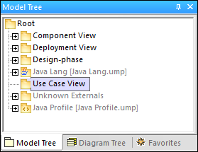
1.Right-click the Root package in the Model Tree window, and select New Element | Package.
2.Enter the name of the new package (in this example, "Use Case View"), and press Enter.
Adding a Use Case diagram to a package
1.Right-click the previously created "Use Case View" package.
2.Select New Diagram | UseCase Diagram.
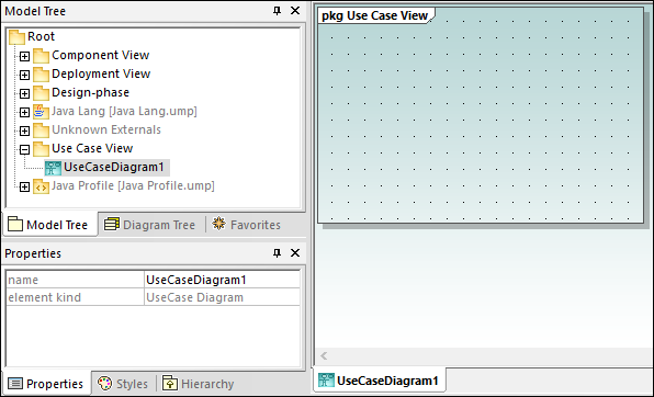
A Use Case diagram has now been added to the package in the Model Tree window, and a new Diagram window has been created as well. A default name has been provided automatically.
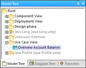
3.Double-click the diagram name in the Model Tree window, change it to "Overview Account Balance", and press Enter to confirm.
Adding Use Case elements to the Use Case diagram
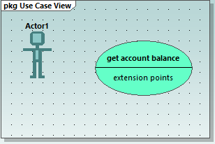
1.Right-click in the newly created diagram and select New | Actor. The actor element is inserted at the click position.
2.Click the Use Case toolbar button ![]() and then click inside the diagram window to insert the element. A "UseCase1" element is inserted. Note that the element, and its name, are currently selected, and that its properties are visible in the Properties window.
and then click inside the diagram window to insert the element. A "UseCase1" element is inserted. Note that the element, and its name, are currently selected, and that its properties are visible in the Properties window.
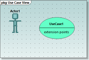
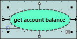
3.Change the title to "get account balance", press Enter to confirm. Double-click the title if it is deselected. Note that the use case is automatically resized to adjust to the text length.
Note: To create a multi-line use case name, press Enter while holding the Ctrl key pressed.
Manipulating UModel elements: handles and compartments
When selected, model elements in a diagram display various connection handles and other items used to manipulate them. Handles can be used to create relationships between elements, or show or hide certain compartments from the element, as shown below.
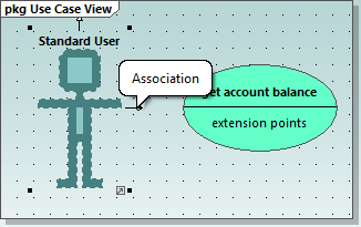
1.Double-click the "Actor1" text of the Actor element, change the name to "Standard User" and press Enter to confirm.
2.Place the mouse cursor over the handle to the right of the actor. A tooltip containing "Association" appears.
3.Click the handle, drag the Association line to the right, and drop it on the "get account balance" use case. An association has now been created between the actor and the use case. The association properties are also visible in the Properties window. The new association has been added to Model Tree under the Relations item of the Use Case View package.
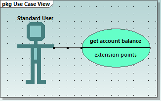
4.Click the use case and drag it to the right to reposition it. The association properties are visible on the association object.
5.Click the use case to select it, then click the collapse icon on the left edge of the ellipse.
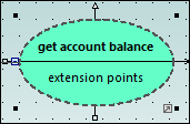
The "extension points" compartment is now hidden.
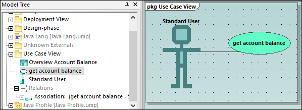
A blue dot next to an element in the Model Tree window signifies that the element is visible in the current diagram. For example, in the image below, three elements are currently visible in the diagram and thus have a blue dot in the Model Tree:
Resizing the actor adjusts the text field, which can also be multi-line. To insert a line break into the text, press Enter while holding the Ctrl key pressed.
To finish up the Use Case diagram:
1.Click the Use Case  toolbar button and simultaneously hold down the Ctrl key.
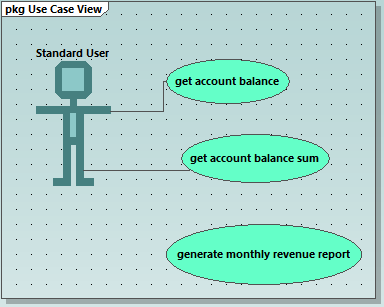
2.Click at two different vertical positions in the diagram to add two more use cases, then release the Ctrl key.
3.Name the first use case "get account balance sum" and the second, "generate monthly revenue report".
4.Click the collapse icon of each use case to hide the extensions compartment.
5.Click the actor and use the association handle to create an association between "Standard User" and "get account balance sum".
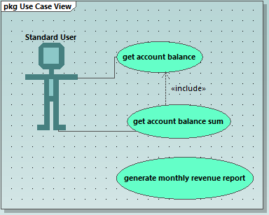
To create an "Include" dependency between use cases (creating a subcase):
•Click the Include handle of the "get account balance sum" use case, at the bottom of the ellipse, and drop the dependency on "get account balance". An "include" dependency is created, and the include stereotype is displayed on the dotted arrow.
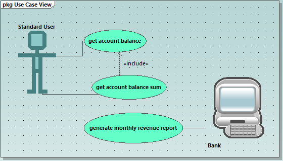
Inserting user-defined (customized) actors
The actor in the "generate monthly revenue report" use case is not a person, but an automated batch job run by a bank computer. The instructions below show to add a new actor to the diagram, and also use a custom image for it.
1.Click the Actor ![]() toolbar button to insert an actor in the diagram.
toolbar button to insert an actor in the diagram.
2.Rename the actor to "Bank".
3.In the Properties window, click Browse ![]() next to "icon file name" entry, and browse for the Bank-PC.bmp file available in the same folder as the project.
next to "icon file name" entry, and browse for the Bank-PC.bmp file available in the same folder as the project.
4.Clear the Absolute Path check box to make the path relative. Select Preview to display a preview of the selected file in the dialog box.
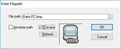
5.Click OK to confirm the settings and insert the new actor. Move the new "Bank" actor to the right of the lowest use case.
6.Click the Association  toolbar button and drag from the "Bank" actor to the "generate monthly revenue report" use case. This is an alternative method of creating an association.
Note: The background color used to make the bitmap transparent has the RGB values 82.82.82.
Aligning and adjusting the size of diagram elements
When dragging components in a diagram, guide lines appear allowing you to align an element to any other element in the diagram. You can enable or disable this option as follows:
1.On the Tools menu, click Options.
2.Click the View tab.
3.In the Alignment group, select the Enable snap lines check box.
You can also align and adjust the size of multiple elements, as follows:
1.Create a selection marquee by dragging on the diagram background, making sure that you encompass all three use cases starting from the top. Alternatively, to select multiple elements, click elements while holding the Ctrl key pressed. Note that the last use case to be marked, is shown in a dashed outline in the diagram, as well as in the Overview window.
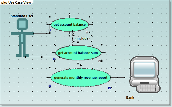
All use cases are selected, with the lowest being the basis for the following adjustments.
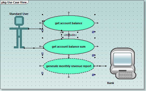
2. Click the Make same size ![]() toolbar button.
toolbar button.
3.To line up all the ovals, click the Center Horizontally ![]() toolbar button.
toolbar button.
Change the style of diagrams in a project
By default, all diagrams of the tutorial project have a gradient background color, and a background grid is also visible. The appearance of diagrams in a project is configurable. For example, to change the background color of all diagrams, do the following:
1.In the Properties window, click Styles.
2.Under Project Styles, identify the setting Diag. Background Color.
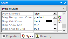
3.Change the value from "gradient" to a color of your choice.
To enable or disable the diagram background grid:
•Change the setting Diag. Show Grid from "true" to "false". (Alternatively, if a diagram is currently open, click the Show Grid  toolbar button.)