Model Tree Window
The Model Tree window enables you to view and manipulate all items (packages, classes, diagrams, relationships, and so on) in the UModel project.
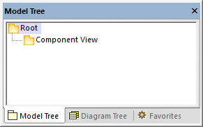
Model Tree window
When you create a new UModel project, two packages are available by default, the "Root" and "Component View" packages. These two packages are the only ones that cannot be renamed or deleted. The "Root" package serves as starting point for modeling all other elements, while the "Component View" package is required for code engineering.
You can create additional packages, classes, diagrams, and their hierarchy either from this window or directly from a diagram, see Creating Elements. For additional operations that you can take against items in the Model Tree, see the How to Model... chapter.
Note: UModel includes several example projects that you can explore in order to learn the modeling basics and the graphical user interface. These can be found at the following path: C:\Users\<username>\Documents\Altova\UModel2025\UModelExamples.
Showing, hiding, and sorting items in the Model Tree
To configure what should be displayed in the Model Tree window, as well as the sorting options, right-click inside the window, and then select the required menu option. To view all actions that can be taken against items displayed in the Model Tree window, right-click the item and observe the context menu options.
Collapsing and expanding items in the Model Tree
To expand items (for example, packages) in the Model Tree window:
•Press the * (asterisk) key to expand the current item and all child items
•Press the + (plus) key to expand the current item only.
To collapse the packages, press the - (dash) keyboard key. To collapse all items, click the "Root" package and press - (dash). Note that you can use both the standard keyboard keys and the numeric keypad keys to achieve this.
Identifying active diagram items
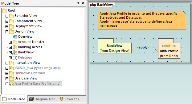
When a diagram is open in the Diagram pane, the Model Tree window shows some items with a light-blue dot at their base. These are items that are displayed in the active diagram (like "BankView" and "Java Profile" in the example below):
Icon reference
The Model Tree window may display a large number of icons which correspond to elements and diagrams in your project, the code engineering packages, as well as the imported profiles or subprojects. Specifically, it may display the following package types:
Icon | Description |
|---|---|
Standard UML Package | |
Java namespace root package. Used to generate or reverse engineer Java code | |
C# namespace root package. Used to generate or reverse engineer C# code | |
C++ namespace root package. Used to reverse engineer C++ code. | |
Visual Basic namespace root package. Used to generate or reverse engineer VB.NET code | |
 | XML Schema namespace root package. Used to generate XML schemas from the model, or import them into the model, see XML Schema Diagrams. |
Database namespace root package. Used to import databases into the model, and change their structure from the model, see UModel and Databases. | |
A namespace package (a package with the <<namespace>> stereotype applied to it) | |
A UML profile |
The diagrams that can appear in the Model Tree window are listed below.
Icon | Description |
|---|---|
Activity Diagram | |
BPMN 1 (Business Process Modeling Notation) Business Process Diagram | |
BPMN 2 Business Process Diagram | |
BPMN 2 Choreography Diagram | |
BPMN 2 Collaboration Diagram | |
Class Diagram | |
Communication Diagram | |
Component Diagram | |
Composite Structure Diagram | |
Database Diagram | |
Deployment Diagram | |
Interaction Overview Diagram | |
Object Diagram | |
Package Diagram | |
Profile Diagram | |
Protocol State Machine Diagram | |
Sequence Diagram | |
State Machine Diagram | |
SysML diagrams (9 diagram types) | |
Timing Diagram | |
Use Case Diagram | |
XML Schema Diagram |
Below are some examples of UML modeling elements that can appear in the Model Tree window. For more information about UML elements and the diagram types where they occur, see the UML Diagrams chapter.
Icon | Description |
|---|---|
Class | |
 | Property |
 | Operation |
Parameter | |
Actor | |
Use Case | |
Component | |
Node | |
Artifact | |
Interface | |
Class Instance (Object) | |
| Class instance slot |
Relations | |
Constraints |