Deployment Diagrams
This tutorial section illustrates the following tasks:
•Add a dependency between two artifacts in a Deployment diagram
•Add elements to a Deployment diagram
•Embed artifacts into a node in a Deployment diagram
•Creating artifact elements (for example, properties, operations, nested artifacts)
To proceed, run UModel and open the BankView-start.ump project (see also Opening the Tutorial Project).
Adding a dependency between two artifacts in a Deployment diagram
In the Diagram Tree window, under "Deployment Diagrams", double-click the icon next to the "Artifacts" diagram to open it. As illustrated below, this diagram shows the manifestation of the Bank API client and the BankView components, to their respective compiled Java .jar files.
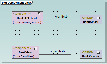
"Artifacts" diagram
These manifestations were created using a technique similar to other relationships previously illustrated in this tutorial, as follows:
1.Click the Manifestation ![]() toolbar button.
toolbar button.
2.Move the mouse cursor over the artifact and drag into the component.
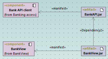
Using the same technique, let's also add a dependency between the two .jar files, as follows:
1.Click the Dependency ![]() toolbar button.
toolbar button.
2.Move the cursor over the BankView.jar artifact and drag into the BankAPI.jar artifact.
3.Select the dependency line and type "Dependency2".
Adding elements to a Deployment diagram
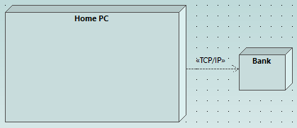
In the Diagram Tree window, under "Deployment Diagrams", double-click the icon next to the "Deployment" diagram to open it. This diagram is deliberately incomplete and consists of a single node, which represents a home PC. In the following steps, we will be adding more elements to this diagram.
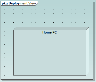
"Deployment" diagram
Assuming that the goal is to illustrate a TCP/IP connection between the home PC and a bank, let's add the required elements:
1.Click the Node ![]() toolbar button, and click right of the Home PC node to insert it.
toolbar button, and click right of the Home PC node to insert it.
2.Rename the node to "Bank", and drag one of its edges to enlarge it.
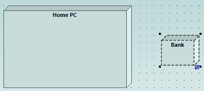
3.Click the Dependency  toolbar button, and then drag from the "Home PC" node to the "Bank" node. This creates a dependency between the two nodes.
4.Select the dependency line and enter "TCP/IP" as name of the new dependency. (Alternatively, edit the Name property in the Properties window).
Embedding artifacts
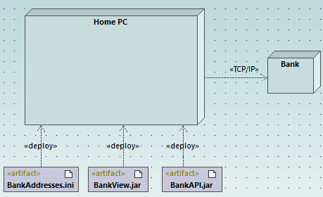
In the Model Tree window, expand the "Deployment View" package, and then drag all of the following artifacts into the diagram: BankAddresses.ini, BankAPI.jar, and BankView.jar. The project is preconfigured to include deploy dependencies between these artifacts and the "Home PC" node, so all these dependencies are now visible in the diagram:
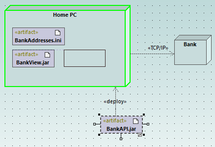
You can also embed the artifacts into the "Home PC" node, by dragging each of the artifacts into it. Notice that the deploy dependencies are no longer visible on the diagram, although they continue to exist logically.
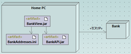
Artifacts embedded into the node can also have dependencies between them. To illustrate this:
1.Click the Dependency toolbar button and, holding the Ctrl key pressed, drag from the "BankView.jar" artifact into the "BankAddresses.ini".
2.While holding the Ctrl key pressed, drag from the "BankView.jar" artifact into the "BankAPI.jar" artifact.
Note: Dragging an artifact out of a node onto the diagram always creates a deployment dependency automatically.
Creating artifact elements (properties, operations, nested artifacts)
In UML, artifacts can be composed of properties, operations, and other elements, including nested artifacts. To create such nested elements, right-click the artifact in the Model Tree window and select the appropriate action from the context menu (for example, New Element | Operation, or New Element | Property). The new element will appear nested below the selected artifact in the Model Tree window.