UModel supports all 14 UML diagrams, as well as a UML diagram for XML Schemas and another to model tables in relational databases, giving your team a powerful UML diagram tool at a fraction of the cost of legacy solutions.
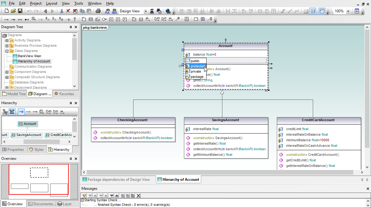
UModel makes class UML diagrams class UML diagrams easy to draw and interpret with color-coded icons and text for each diagram element, intelligent entry helpers, and intuitive element relationship tools.
A UML object diagram represents a single example of a class and is used to illustrate one datapoint in your application. When you create a new object, called an instance specification, UModel lets you assign an existing class represented by the instance. UModel automatically supplies instances of the appropriate properties from the defining class to the object, and you can then insert sample values for your object.
Component UML diagrams map the logical view of the project classes to the actual files containing the source code where the logic is implemented. When UModel generates code, the component diagrams represent the location of the Java, C++, C#, or Visual Basic source code files for your classes. When reverse engineering an existing project, the component diagrams can help you correlate each UModel class diagram with the source code files.
A composite structure diagram illustrates a conceptual design and raises the level of abstraction by communicating the design strategy without referencing any particular programming language, operating system, or other specific implementation details.
UML Deployment diagrams provide a picture of the physical architecture of the hardware, software, and artifacts of the system. Deployment diagrams can be thought of as the opposite end of the spectrum from use cases, depicting the physical form of the system as opposed to conceptual pictures of users and devices interacting with the system.
You can direct UModel to generate a package dependency diagram for any package in the Model Tree, or easy create package diagrams yourself. The UModel package diagram toolbar enables quick entry of packages, profiles, and package relationships: package dependency, package import, package merge, and profile application.
Shown above is a UML package dependency diagram automatically generated by UModel. UModel added a hyperlink to the Design View package element, so any other diagram in the project that includes the Design View package will also automatically include a convenient link to the package dependency diagram.
UModel lets you create profile diagrams to illustrate application of profiles containing source code language types and other constructs, as well as to define custom stereotypes for special applications. UModel includes language profiles for C#, Visual Basic, and Java languages. Language profiles are provided in generic and version-specific alternative variations.
UML sequence diagrams describe the interactions between objects in an application and the messages objects send and receive. The UModel sequence diagram toolbar provides quick access to specialized UML elements including lifelines, combine fragments, gates, message call and reply arrows, message arrows that create new lifelines or destroy existing objects, notes, and more.
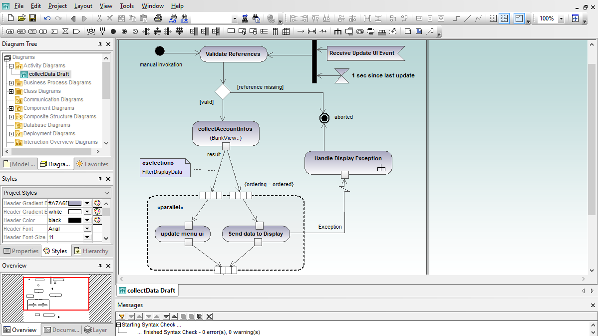
The UML 2 specification greatly expanded the features and scope of activity diagrams beyond their earlier classification as a special case of state diagrams. Today, activity diagrams are flow charts for the 21st century, and UML modelers use activity diagrams to describe business rules, single use cases, a complex series of multiple use cases, processes with decision points and alternate flows, operations that take place in parallel or software flows and logic control structures.
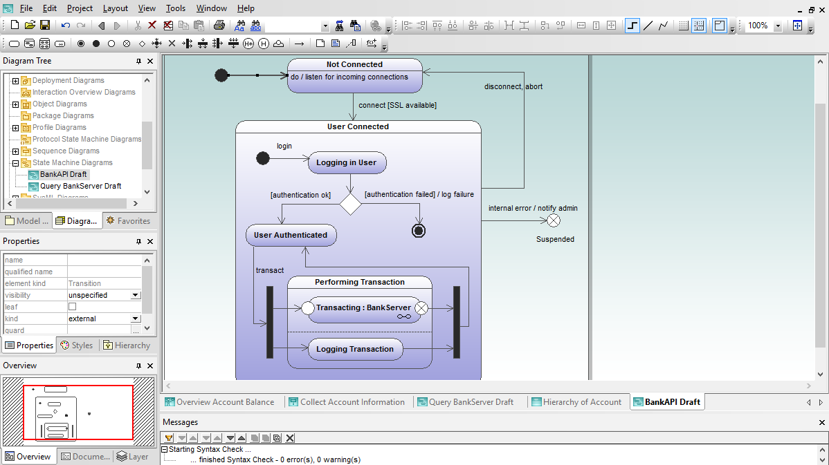
State machine diagrams identify states and transitions of an object as It proceeds through its life cycle. State machine diagrams (also called state diagrams) are a traditional object-oriented way to show behavior and to document how an object responds to events, including internal and external stimuli.
Whether you are planning the logic of a business object such as in invoice – whose states might be issued, paid, or overdue – or the behavior of a complex hardware-based system, you'll find UModel to be an intuitive and enjoyable tool as you develop your state machine diagrams.
UML Protocol state machine diagrams are a subset of state machine diagrams that display a sequence of events an object responds to, without having to show the specific behavior. Protocol state machines are most often used to describe complex protocols, such as database access through a specific interface, or communication protocols such as TCP/IP.
Although you can create protocol state machine diagrams using existing state diagram elements, state diagram history elements are not employed, and other elements imply slightly different syntax. For instance, transitions between states can have pre- or post- conditions that define what must be true for a transition to another state to occur, and what the resulting state must be after the transition has taken place.
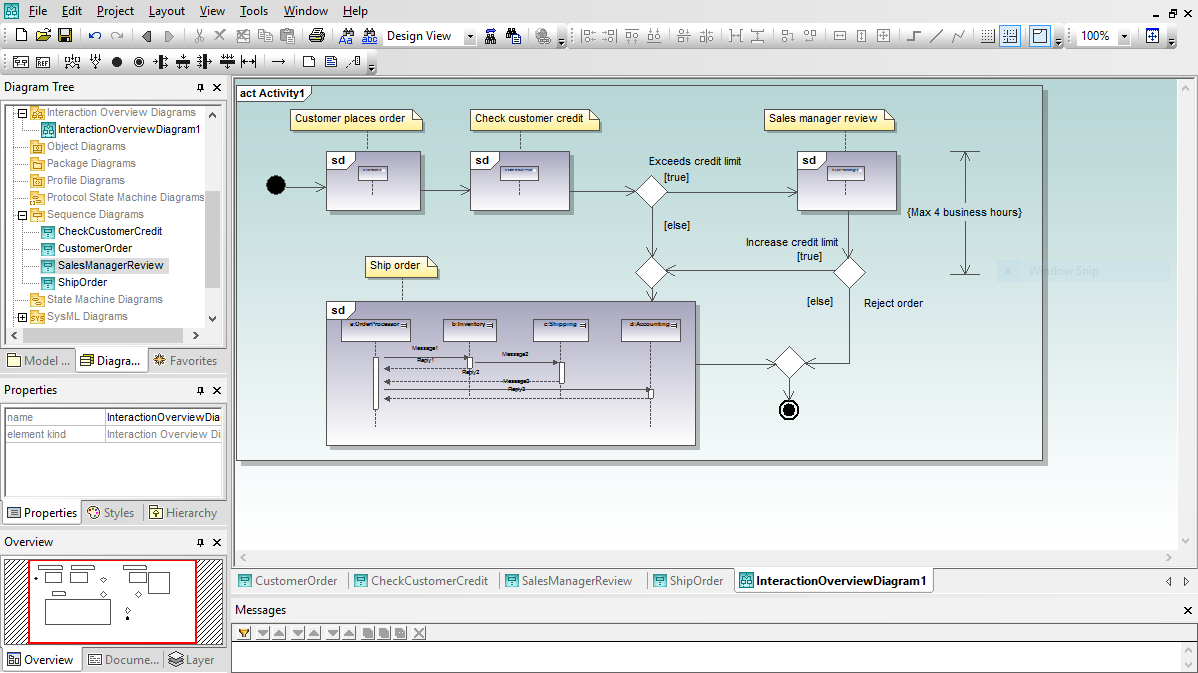
UML interaction overview diagrams present a high-level view of execution paths through an application. UML interaction overview diagrams combine elements of activity diagrams with sequence diagrams to show the flow of program execution. You can also use an interaction overview diagram to deconstruct a complex scenario that would otherwise require multiple if-then-else paths to be illustrated as a single sequence diagram.
UML timing diagrams are based on hardware timing diagrams developed for electrical engineering. Software modelers use a UML timing diagrams to precisely document a schedule of interactions or state changes in a system. As you start constructing a timing diagram in UModel by clicking the lifeline icon in the timing diagram toolbar, you’ll find familiar visual tools and intuitive selections in the right-click context menu to resize the lifeline and add new states, duration and time constraints, tick marks, and event stimulus elements.
UModel supports both area style and line notation for timing diagram, with a Toggle Notation to convert existing diagrams. As always, if you don't like the results you can click the Undo button to go back.
Communication diagrams describe messages transmitted between objects and imply associations between classes. UML communication diagrams are similar to sequence diagrams, but provide an overview of the relationships between objects, rather than focusing on the order of messages between objects, as your software executes.