Altova UModel is the starting point for successful software development.
Altova UModel is the UML tool that makes visual software design practical for any project. Visually design application models in UML and generate Java, C++, C#, or Visual Basic .NET code and project documentation. Or, reverse engineer existing programs into UML diagrams, then enhance your designs and complete the round trip by regenerating code.
UModel is the affordable UML tool that combines a rich visual interface with high-end functionality like source code engineering, XMI model interchange, support for Business Process Modeling, and more, to give development teams a powerful tool for today's project challenges.
New! Update database support and more new features in Version 2026 available October 21, 2025.
“I'm very happy with UModel. Finally a UML modeling tool that is affordable and that works the way I like!”
“UModel brings the 'Wow factor' to UML!”
Keep your favorite diagram views and UML tools at your fingertips to improve efficiency and productivity. Everything is customizable in the UML diagrams you create with UModel – size, position, color, typeface characteristics, and line styles.
UModel supports all 14 UML 2.5 software architecture diagram types, plus UML-style diagrams for XML Schemas and tables in popular SQL databases.
Use case diagrams are often considered separately from other software architecture diagrams because they capture project requirements and can define the scope of an application under development.
It’s not likely any project will use all UML diagram types – software modeling allows flexibility in preferences and styles, and various tasks require different diagram types. Regardless which diagrams you create, UModel provides an unmatched visual interface and convenient features to make UML modeling easy and fun.
The styles window in UModel gives you easy access to all the display options and lets you modify an individual element, a selected group, or an entire category. You can also choose colors from a palette in a pull-down menu, or easily assign custom colors to elements either individually, across groups and families, or for the entire project.
UModel's flexible layout options let you give your models the clearest, most logical organization. The alignment grid forms a background framework to position diagram elements. As you create new elements or move existing ones across the main drawing pane, visual alignment snap lines help you align with other existing elements in the diagram.
Each diagram type has its own toolbar, so the screen won’t be crowded with irrelevant icons. You can turn toolbar text labels on or off and you can display or hide any toolbar.
UModel even includes unlimited undo/redo to encourage exploring new ideas!
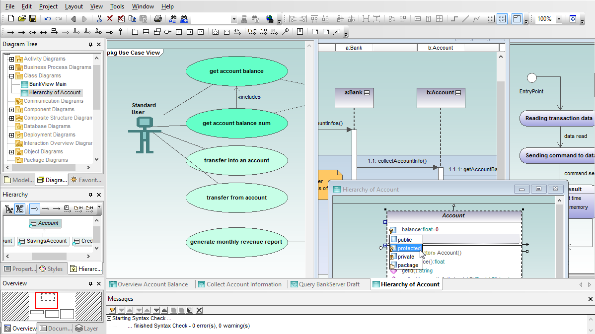
Helper windows at the left of the main diagram assist as you build and view your models. You can select a perspective into the project by choosing from the Model Tree, Diagram Tree, or Favorites.
Other windows provide quick access to Properties, Styles, Hierarchy, and Overview, a navigation aid for large diagrams.
UModel allows you to add hyperlinks to any element in any UML diagram. You can create hyperlinks to external files, Web URLs, or other diagrams in your project. Your description becomes pop-up text for the hyperlink.
UModel supports diagram layers. Each element can be assigned to a specific layer, and layers can be locked to prevent changes.
The Overview helper window displays a reduced view that identifies which portion of a large diagram is displayed in the main diagram pane, providing a quick navigation tool for complex diagrams that are too large to display. Click inside the window to scroll in any direction.
UModel includes a built-in code generator that creates Java, C++, C#, or Visual Basic .NET code based on the class diagrams, sequence diagrams, and state machine diagrams in your UML model, freeing you from the mundane task of writing low level infrastructure code so you can concentrate on the business logic and overall architecture of your project.
Take advantage of the source code generated by UModel to accelerate the implementation phase of your project and eliminate the unintended errors that can creep into manually written code and prove time-consuming to debug later on.
The UModel code generator is based on the same technology used in XMLSpy and MapForce. Supplied Java profiles generate industry-standard Java code compatible with Eclipse, Borland® JBuilder®, and other popular Java development environments. Profiles for C++ are compatible with Visual Studio, and profiles for C# generate code for Microsoft® Visual C# .NET®, Borland® C#Builder®, or other C# development environments. Profiles for Visual Basic .NET support VB code gen.
UModel supports C# generics with strong type checking and instantiation at runtime, and provides compatibility for new language constructs introduced in C# 3.0 and VB 9.0 that directly support XML. UModel also supports named arguments, optional parameters, dynamic programming, co- and contravariance introduced in C# 4.0 during round trip engineering, binary import and sequence diagram generation.
Java developers will appreciate support for Java generics as UML templates and Java enumerations, permitting easier definition of collections where all elements are the same type and allowing type errors in those collections to be detected at compile time.
To ensure code quality, UModel includes a model syntax checker to detect diagram errors or inconsistencies before they are replicated downstream in code.
UModel creates Java, C++, C#, or Visual Basic .NET code based on the classes in your UML model, freeing you from the mundane task of writing low level infrastructure code, so you can concentrate on the business logic and overall architecture of your project.
Take advantage of the source code generated by UModel to accelerate the implementation phase of your project and eliminate the unintended errors that can creep into manually written code and prove time-consuming to debug later on.
UModel empowers developers to generate code from sequence diagrams for methods that describe class operations. Developers can insert entire code bodies in sequence diagrams and create a complete executable application, rather than simply a starting point that requires further hand-written code.
You can generate source code from new UML sequence diagrams when forward engineering a new design, update existing code by revising sequence diagrams that were reverse-engineered, and you can even apply round-trip engineering to synchronize later changes to either the source code or sequence diagrams in your UML model.
UModel code generation from sequence diagrams is supported for Java, C++, C#, and Visual Basic languages.
When you add a new message to a lifeline that represents a class, you can assign a message name or select an existing operation in the target class from the Properties window.
If you turn on Automatic Creation of Operations in the Sequence Diagram toolbar, you can simultaneously create a new operation in the class when you type the name of the new message in your sequence diagram.
UModel lets you generate code from state machine diagrams that is fully executable, so you can quickly begin testing the logic captured in your state machine diagram.
You can generate code either as part of the normal project code generation process, via a selection in the Project menu, or directly from the state machine diagram context menu.
The UModel context menu also provides an option to let you check the state machine diagram syntax, to avoid generating code that is not valid.
The Generate State Machine Code dialog box lets you control code generation settings, and even specify whether state machine code is automatically regenerated with project code generation.
When you add a new transition to a state machine diagram that is inside a class or interface, you can use a pull-down list in the Properties window to assign an existing operation from the target class.
The option labeled Automatic Creation of Operations in the State Machine Diagram toolbar lets you simultaneously create a new operation in the class as you name the new operation in your state machine.
The sample project files installed with UModel even include Visual Studio solution files for C# and Visual Basic, and a Java tester application that demonstrates execution of the state machine code and is easily adaptable to use with your own state machine diagrams.
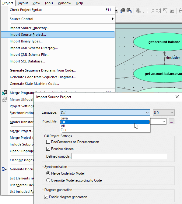
UModel includes a powerful reverse engineering capability to read Java, C#, C++ and Visual Basic source code and binary files, and generate UML models for a visual representation that is much clearer and more easily analyzed than a printout of the source as text.
You can apply reverse engineering to model an existing application, or get a new project off to a quick start by importing class libraries such as employee, customer, vendor, and other classes that your team has already developed.
UModel can import Java source code files from JBuilder, Eclipse, and NetBeans projects, C++ source code from Microsoft Visual Studio, C# source code from Visual Studio and Borland C#, and Visual Basic .NET project files.
You can import a single directory, a directory tree, or an entire project, and you can choose to merge the imported code into an existing UModel project, or create a new one.
If you import Java source code that has accompanying JavaDocs, the UModel documentation window can be optionally populated for each UML diagram. Similarly, C# and Visual Basic .NET DocComments can also be imported as documentation for your model project.
UModel reverse engineering of Visual Basic .NET code is line-oriented and case-insensitive (so Class1, CLASS1, class1, ClAsS1 are considered as identical), consistent with looser Visual Basic .NET naming requirements.
UModel can import Java, C++, C#, and Visual Basic .NET binary files. For Java, type import is supported for all class archives adhering to the Java Virtual Machine Specification.
For C#, type import is supported for assemblies targeting the .NET Framework, .NET Core, and .NET Compact Framework for PocketPC, Smartphone, and WindowsCE. For Visual Basic .NET, DLLs and EXEs from the filesystem, or an assembly from the global cache (GAC) or from a MSVS.NET reference can be imported.
Additional binary import options may be available, depending on the requirements of the specific binaries you select. The UModel integrated Help system can guide you through all the details of importing binary files.
UModel lets you generate sequence diagrams from source code files that have been reverse engineered into UML classes, an invaluable aid to analysis of complex interactions.
You can automatically split very large sequence diagrams and hyperlink them for convenient navigation.
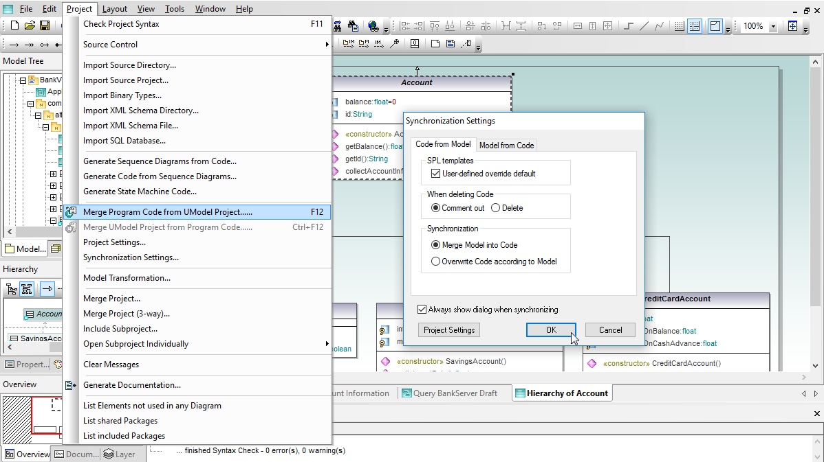
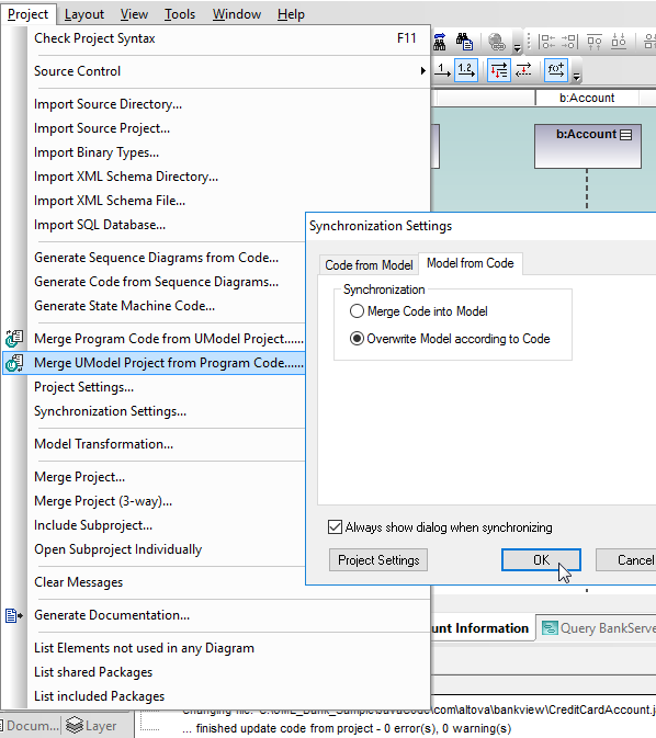
As your project evolves, you will modify and add to the original base of generated source code by working directly in the Java, C++, C#, or Visual Basic .NET sources using your favorite IDE. The UModel round-trip engineering capability reads the modified code and automatically updates your UML diagrams accordingly. This synchronization keeps your model accurate and relevant as the code changes.
UModel does not require any pseudo-code or special comments in the source code to perform successful round-tripping. This leaves your code free of artifacts that can make it harder to understand or edit directly.
UModel round trip engineering supports an iterative development process. After you synchronize the model with revised code, you are still free to choose the best way to work – make further modifications to the code or make changes to your model. You can synchronize in either direction at any time and repeat the cycle as many times as necessary.
Like all other UModel features, round trip engineering supports unlimited undo/redo. You’re free to experiment with all the dialog checkbox options, knowing that you can restore your model with just a click.
UModel integration functionality raises round-trip engineering to the next level. When using UModel Enterprise Edition inside Microsoft® Visual Studio® or the Eclipse integrated development environment (IDE), a developer can open a UModel project in one window and the associated application code in a source code editor in another.
Automatic synchronization can be set in either or both directions to instantly update the UML model or source code whenever changes are made to the other. This allows developers to immediately see the impact of application revisions, whether implemented in the model or directly in source code.
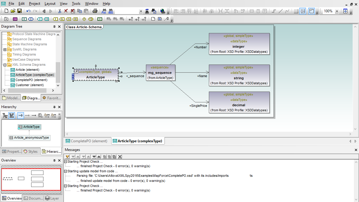
UModel includes a special diagram type and code generation support for XML schemas. The UModel XML Schema diagram renders XML Schemas in a format similar to UML class diagrams, displaying XML schema global elements (elements, simpleTypes, and complexTypes) as classes with schema element attributes in the attributes compartment.
UModel uses UML notes to display schema details. When you import an XML Schema it is treated as application source code and reverse-engineered to create a UModel project. The project file and the diagrams it contains are a model of the XML Schema, not the schema itself.
Since the UModel project and the XML Schema are separate files, the UML model of the schema provides a level of abstraction between the schema design and the actual XSD. This allows developers working in teams to develop schema enhancements in a collaborative process by modifying the UModel project, treating the UML model as a blueprint. Changes made to the XML Schema design in the model are written back to the XML Schema file (*.xsd) during code generation or project synchronization.
UModel also supports round-trip engineering for XML Schema files. If the schema is modified outside UModel you can use the UModel Project menu to synchronize changes back to the UModel project and XML diagram.
If your project requires you to design a new XML Schema, you'll want to check out the specialized schema editing and validation features of Altova XMLSpy, the industry-standard development environment for XML.
One developer on your team can work on the XML schema in XMLSpy, and other developers can synchronize their models by round-trip engineering the XSD file. If your project requires you to design a new XML Schema, you'll want to check out the specialized schema editing and validation features of Altova XMLSpy, the industry-standard development environment for XML.
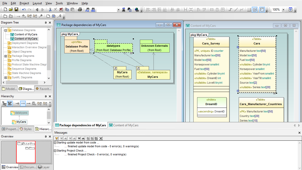
As software applications interact with growing amounts of data, database designs and structures become critical to development of successful projects. UModel empowers you to import existing tables from all popular relational databases to create UML database diagrams, modify diagrams for existing tables and generate SQL database change scripts to synchronize the database, or design new database tables and relationships from scratch and issue SQL CREATE scripts.
You can easily import an entire relational database in a single step, or choose only the tables in the database that are relevant to your project, to model data structures along with your software application.
The UModel database diagram functionality supports multiple databases and automatically adjusts SQL dialects, data types and other specialized features based on the database type. UModel supports these database elements: database schemas, tables, views, check constraints, primary / foreign / unique keys, indexes, stored procedures, functions, triggers, database relationship associations, and database relationships with attributes.
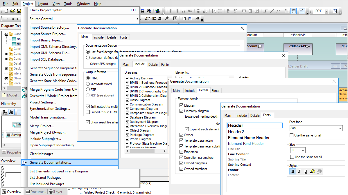
Documentation is an important part of your software development. UModel accelerates this requirement by automatically generating project documentation in HTML, Microsoft Word, or rich text (RTF) formats.
The UModel built-in project documentation design offers a high level of user control, flexibility, and customization. After selecting output format and image processing options, you can customize the project documentation for your needs. You can also select the level of detail to include for each element, such as including Hierarchy diagrams to assist communication of class relationships.
Whichever output format you choose, UModel adds hyperlinks within the documentation to aid navigation. Links to the generated source code files are also included. The UModel built-in documentation design also lets you control the appearance of project documentation by individually specifying the type style and size of each text block.
If your documentation needs require greater customization, you can use an SPS stylesheet to instruct Altova StyleVision to create completely customized documentation for your UML project.
UModel includes a sample stylesheet that can be the starting point for your own customized format using all the flexibility of StyleVision. A stylesheet can let you embed images into your UML project documentation – such as your company logo – and headers, footers, or blocks of standard text. Stylesheet-based documentation also supports PDF output.
You can select a stylesheet in the UModel Generate Documentation dialog and send execution instructions directly to StyleVision to create customized documentation in a workflow that is completely automated.
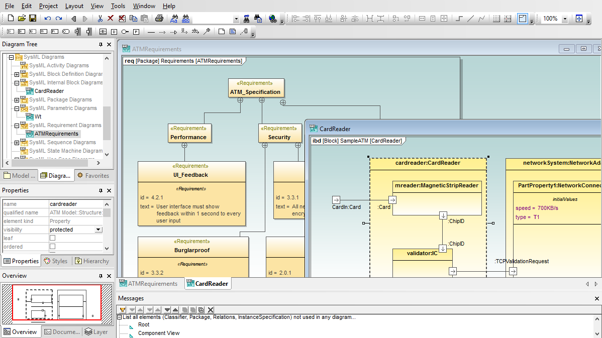
UModel supports SysML™ modeling for embedded systems and other complex devices.
As an embedded system receives inputs and produces output, its internal operations and states can be opaque. This can make software to control embedded systems difficult to develop, test, and debug. Software modeling with Altova UModel and SysML lets you create a traceable blueprint that is useful for planning, designing, and documenting the system under development.
SysML diagrams can be divided into three types: diagrams that capture system requirements and physical constraints, diagrams that describe the structure of the system, and diagrams that describe the behavior of the system. UModel supports all SysML diagrams and extensions:
As communication supporting various business activities accelerates, it becomes more and more critical to have a standard modeling system that can be easily read and understood by a variety of users at a broad range of levels within business organizations, yet can be used to represent complex processes involving multiple parties or enterprises.
Business Process Modeling Notation is a graphical standard for creating flow chart-like diagrams that are readily understandable by all business stakeholders including business analysts, technical developers, and business managers. The BPMN standard is maintained by the Object Management Group (OMG), the same organization that administers UML.
UModel supports both BPMN 1.0 and BPMN 2.0 notation, and even provides a migration path for users who want to update older diagrams with new elements and functionality introduced in the BPMN 2.0 standard. UModel also supports BPMN model exchange with other BPMN tools through the XMI specification first developed for UML models.
UModel BPMN Features:
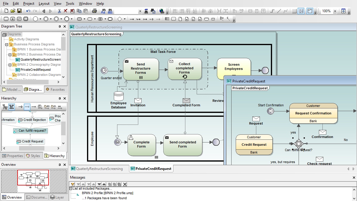
The elements and rules for business process diagrams are very similar to UML activity diagrams, providing a natural transition of the easy to use and highly acclaimed drawing tools of UModel from UML to Business Process Modeling Notation. UModel lets you create free-form diagrams that are useful for capturing the details of an internal process.
Choreography diagrams specify the way business participants coordinate their interactions. Choreographies can also be seen as a business contract between participants, where the focus lies on the exchange of information (messages) between the participants
The UModel choreography diagram toolbar provides quick access to all BPMN 2.0 choreography elements with drop-down selection of task, event, and gateway variations.
Collaboration Diagrams specify the interactions between two or more processes. A BPMN collaboration generally consists of two or more pools which represent the participants in the collaboration. Message exchanges between participants are shown by Message Flows that connect the two pools, or the objects within the pools. The UModel collaboration diagram toolbar provides quick access to all collaboration diagram elements.