Generate Sequence Diagrams from Source Code
This example shows you how to generate a Sequence diagram from a method. The project containing this method will be reverse-engineered from Java source code. You can find the Java source code at the following path: C:\Users\<user>\Documents\Altova\UModel2024\UModelExamples\OrgChart.zip. First, unzip the OrgChart.zip archive to the same location (for example, right-click the archive in Windows Explorer and select Extract All).
1.On the Project menu, click Import Source Directory, and select the directory unzipped previously.
2.Go through the wizard steps to import the source code as a Java project. For more information about this step, see Reverse Engineering (from Code to Model).
3.Having imported the code, right-click the main method of the OrgChartTest class in the Model Tree and select Generate Sequence Diagram from Code... from the context menu.
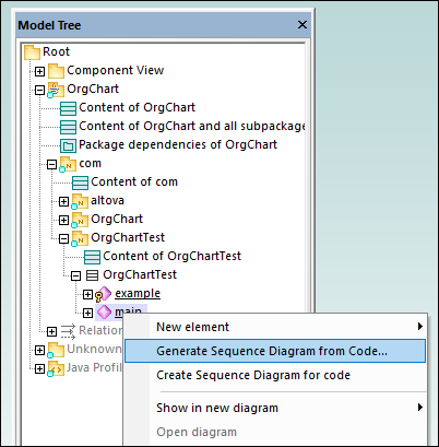
This opens the Sequence Diagram Generation dialog box in which you define the generation settings.
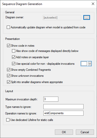
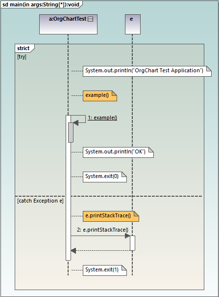
4.Select the presentation and layout options, and then click OK to generate the diagram. The settings shown above produce the sequence diagram below.
Sequence diagram generation options
The table below lists the generation options pertaining to Sequence diagrams.
Option | Purpose |
|---|---|
Diagram owner | You can set this option when generating a diagram for the first time. For existing diagrams, this information is read-only.
Click the Ellipsis button to select the owner package of the diagram. Otherwise, the option [autoselect] places the diagram in the default package. |
Automatically update diagram when model is updated from code | When you perform reverse engineering (from code to model), sequence diagrams are re-generated automatically in the model, provided that you have selected the option Automatically update diagram when model is updated from code when generating the diagram for the first time.
For existing diagrams, you can change this option as follows:
1.Select the Sequence diagram in the Model Tree or in the Diagram Tree. 2.In the Properties window, select the update on reverse engineering check box. 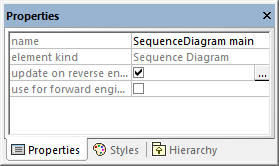 If you select the use for forward engineering check box, the synchronization from model to code will generate code based on the sequence diagram, when you perform forward engineering (from model to code), see also Generate Code from Sequence Diagram.
If the two "engineering" check boxes are missing, it is likely that this diagram is just a fragment of a bigger diagram, or perhaps you have created the diagram from a non reverse-engineered operation. |
Show code in notes | Select this check box to generate the diagram with notes (callouts) that contain program code. |
Also show code of messages displayed directly below | Even when it is possible to show a piece of code as UML Message on the diagram, this option still displays the code of that message as a note. |
Add notes on separate layer | Assigns code notes to a "Code Annotations" layer.
 |
Use special color for non-displayable invocations | Assigns a color of your choice to non-displayable invocations. |
Show empty Combined Fragments | Keeps the Combined Fragment blocks on the diagram, even if they don't contain anything. |
Shown unknown invocations | When selected, this option also displays messages for operations or constructors which could not be resolved (that is, not found in the model). |
Split into smaller diagrams where appropriate | Automatically splits sequence diagrams into smaller sub-diagrams, and automatically generates hyperlinks between them for easy navigation. |
Maximum invocation depth | Defines the call depth to be used in the diagram. For example, if method1() calls method2() which calls method3(), and the invocation depth is set to 2, then only method2 is shown, and method3 is no longer shown. |
Type names to ignore | Lets you define a comma delimited list of types that should not appear in the sequence diagram when it is generated. |
Operation names to ignore | Lets you define a comma delimited list of operations that should not appear in the generated sequence diagram. Adding the operation names to the list causes the complete operation to be ignored. Prepending a "+" character to the operation in the list (for example, +InitComponent) causes the operation calls to be shown in the diagram, but without their content. |
Use dedicated Lifeline for static calls | If there are static methods calls, and if there is already an instance of that object on the diagram, messages are normally drawn to that existing lifeline. With this option enabled, the diagram generator uses a dedicated new lifeline just for static method calls for that classifier. |