Creating states, activities and transitions
To add a simple state:
1.Click the State toolbar icon ( ![]() ) , and then click inside the diagram.
) , and then click inside the diagram.
2.Enter the name of the state and press Enter to confirm.
To add an activity to a state:
•Right-click the state element, select New, and then one of the entries from the context menu.
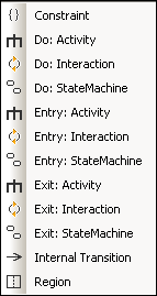
The Entry, Exit, and Do activities are associated with one of the following possible behaviors: "Activity", "Interaction", and "StateMachine". Therefore, the options available in the context menu are:
•Do: Activity
•Do: Interaction
•Do: StateMachine
•Entry: Activity
•Entry: Interaction
•Entry: StateMachine
•Exit: Activity
•Exit: Interaction
•Exit: StateMachine
These options originate in the UML specification. Namely, each of these internal actions are behaviors, and, in the UML specification, three classes derive from the "Behavior" class: Activity, StateMachine, and Interaction. In the generated code, it does not make a difference which particular behavior (Activity, StateMachine, or Interaction) has been selected.
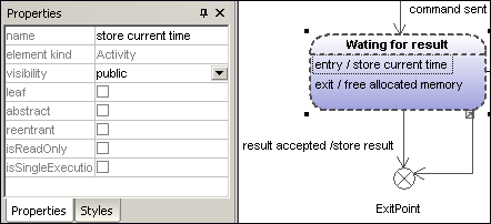
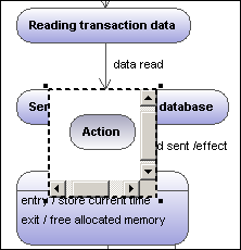
You can select one action from the Do, Entry and Exit action categories. Activities are placed in their own compartment in the state element, though not in a separate region. The type of activity that you select is used as a prefix for the activity e.g. entry / store current time.
To delete an activity:
•Click the respective activity in the state element and press the Del key.
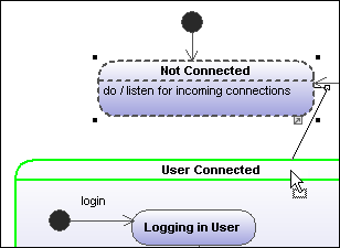
To create a transition between two states:
1.Click the Transition handle of the source state (on the right of the element).
2.Drag-and-drop the transition arrow onto the target state.
The Transition properties are now visible in the Properties tab. Clicking the "kind" combo box, allows you to define the transition type: external, internal or local.
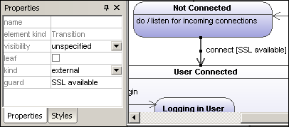
Transitions can have an event trigger, a guard condition and an action in the form eventTrigger [guard condition] /activity.
To automatically create operations from transitions:
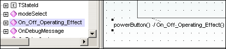
Activating the "Toggle automatic creation of operations in target by typing operation names" icon ![]() , automatically creates the corresponding operation in the referenced class, when creating a transition and entering a name e.g. myOperation().
, automatically creates the corresponding operation in the referenced class, when creating a transition and entering a name e.g. myOperation().
| Note: | Operations can only be created automatically when the state machine is inside a class or interface. |
To automatically create operations from activities:
| 1. | Right click the State and select the specific action/activity, e.g. New | Entry:Activity. |
| 2. | Enter the name of the activity making sure to finish with the open/close brackets "()", e.g. entry / OnEntryCooler(). |
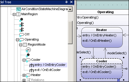
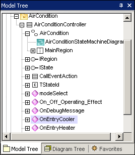
The new element is also visible in the Model Tree. Scrolling down the Model Tree, you will notice that the OnEntryCooler operation has been added to the parent class AirConditionController.
| Note: | Operations are automatically added for: Do:Activity, Entry:Activity, Exit:Activity, as well as guard condition activities and effects (on transitions). |
To create a transition trigger:
1.Right-click a previously created transition (arrow).
2.Select New | Trigger.
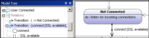
An "a" character appears in the transition label above the transition arrow, if it is the first trigger in the state diagram. Triggers are assigned default values of the form alphabetic letter, source state -> target state.
3.Double-click the new character and enter the transition properties in the form eventTrigger [guard condition] / activity.
Transition property syntax The text entered before the square brackets is the trigger; the text between brackets is the guard condition, and the text after the slash—the activity. Manipulating this string automatically creates or deletes the respective elements in the Model Tree. |
| Note: | To see the individual transition properties, right-click the transition (arrow) and select "Select in Model Tree". The event, activity and constraint elements are all shown below the selected transition. |
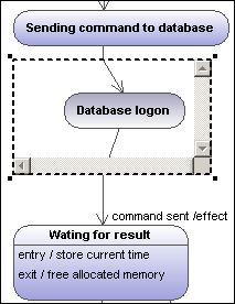
Adding an Activity diagram to a transition
UModel has the unique capability of allowing you to add an Activity diagram to a transition, to describe the transition in more detail.
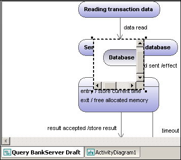
1.Right-click a transition arrow in the diagram, and select New | Activity Diagram. This inserts an Activity diagram window into the diagram at the position of the transition arrow.
2.Click the inserted window to make it active. You can now use the scroll bars to scroll within the window.
3.Double-click the Action window to switch into the Activity diagram and further define the transition, e.g. change the Action name to "Database logon". Note that a new Activity Diagram tab has now been added to the project. You can add any activity modeling elements to the diagram, please see "Activity Diagram" for more information.
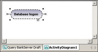
4.Click the State Machine Diagram tab to switch back to see the updated transition.
5.Drag the Activity window to reposition it in the diagram, and click the resize handle if necessary.
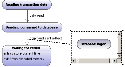
Dragging the Activity window between the two states displays the transition in and out of the activity.