Block Definition Diagram
Block Definition Diagrams are based on the UML Class Diagrams, with restrictions and extensions as defined by SysML. The Block Definition Diagram presents structural elements called "blocks", and their relationships, such as associations, generalizations, and dependencies.
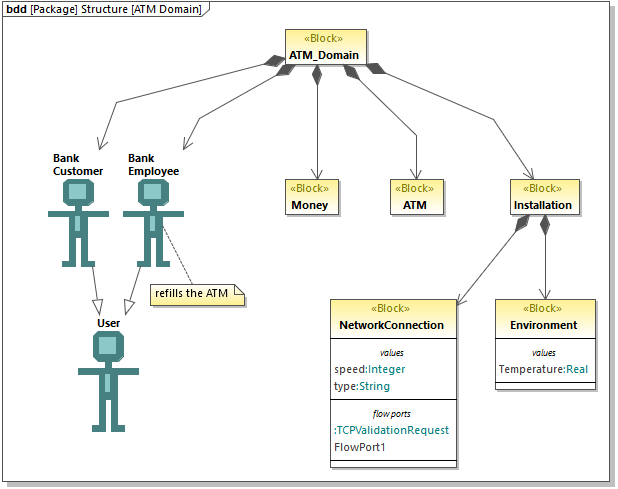
Block Definition diagram
Blocks are fundamental units for describing structure in SysML; they are similar to classes in UML class diagrams. Blocks may include components such as parts, operations, properties and ports. A property can be specialized; for example, it can be a PartProperty, a ReferenceProperty, or a ValueProperty.
To create a block:
1.Create a new Block Definition diagram, see Creating SysML diagrams.
2.Do one of the following:
oRight-click an empty area in the diagram, and select New | Block from the context menu.
oClick the Block ![]() toolbar button and then click inside the diagram.
toolbar button and then click inside the diagram.
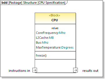
To add a property to a block:
•Right-click an existing block and select New | Property (or PartProperty, ReferenceProperty, ValueProperty, as applicable) from the context menu.
A new compartment is added to the block, for example, "parts" for a PartProperty, or "values" for a ValueProperty.
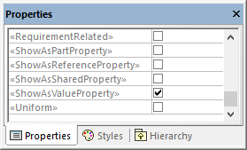
You can change at any time the specialization of an existing property (for example, you can convert a PartProperty to a ValueProperty). To do this, first select the property on the diagram or in the Model Tree, and then select the check box with an appropriate stereotype in the Properties window, for example:
To show block properties as nodes:
•Right-click a block and select Show | Show properties as nodes on node.
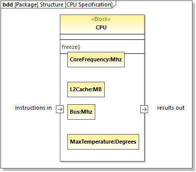
To undo the action above, right-click a property (for example, Bus:Mhz in the image above), and select Delete from diagram only from the context menu.