Agile development is quickly becoming a leading model in the forward-thinking software community. The agile method seeks to bring development out of the document-heavy rigidity that exists within architecture-centric projects with a flexible and lightweight alternative that focuses heavily on adaptivity and customer communication. The agile model seeks to reduce the vast amounts of paperwork and planning put into many software development projects, shifting the focus to adapt to changing requirements and overall customer satisfaction. The Unified Modeling Language™ (UML®) has long been the de facto industry standard for object oriented software modeling, offering thirteen diagram types to represent three different system views: structure, behavior, and interaction. Altova’s UML modeling tool, UModel, presents an approach to UML that is both iterative and flexible, giving software documentation the ability to adapt and change with each new iteration, and offering customer-facing development teams the opportunity to present compelling application model designs every step of the way.
UML
Adopted as a standard by the Object Management Group (OMG) in 1997, and later formalized as ISO 19805, UML is actually the product of several different prevalent OO modeling languages which emerged in the early 1990s. UML is a graphical language for organizing, analyzing, and planning object-oriented or component-based software projects. The UML 2.1 specification defines thirteen major different diagram types and over one thousand graphical and textual language elements, as well as additional extension mechanisms. Traditionally these diagrams have been used by software developers and project managers as a powerful, standardized planning language to verify application logic and confirm that end-user needs will be met. UML is complex by design, offering a multitude of options for visually detailing software implementations in a wide variety of hierarchical models that can provide representations for every stage and process within the development cycle. Structure Diagrams
- Class diagram
- Component diagram
- Composite structure diagram
- Deployment diagram
- Object diagram
- Package diagram
Behavior Diagrams
- Activity diagram
- State machine diagram
- Use case diagram
Interaction Diagrams
- Communication diagram
- Interaction overview diagram
- Sequence diagram
- Timing diagram
With this complexity comes a learning curve that can be easily addressed by choosing an intuitive UML modeling tool that includes advanced usability features and seamless graphical representations, as well as the agility to adapt and grow with a software development project. The Agile Manifesto Drafted in early 2001, the Agile Manifesto documents a set of principles for a faster, lighter, and goal-oriented approach to software development that contrast with the traditional waterfall method that has long existed at a majority of technology companies. The ideas behind agile development had been gaining notoriety over many years with the creation of other similar lightweight methodologies, many of which have since been incorporated into the agile family. The manifesto is built on the concept of software development as an iterative process that must be able to quickly adapt to ever-changing requirements and customer needs. The document focuses on:
- Individuals and interactions over processes and tools
- Working software over comprehensive documentation
- Customer collaboration over contract negotiation
- Responding to change over following a plan
An adherence to these overall goals intends to keep software projects limber and malleable enough to adapt to changing requirements, while keeping developers focused on the quality of their work at every stage of the process. Agile Modeling The agile methodology requires a modeling and documentation process that reflects the fluidity of its founding principles. The agile modeling process is a means to support development projects, addressing interaction and collaboration through the presentation of action plans in a visual format that stakeholders can readily understand, while also being technical enough to provide developers with a basis for their design. Agile modeling focuses on simplicity and the ability to process and handle changing requirements, leading to an incremental approach, where software projects are visually modeled and presented in phases, rather than a traditional model in which all encompassing plans are drawn up at the outset. The Agile Model Driven Development (AMDD) approach dictates a relatively short requirements analysis phase, with successive just-in-time modeling to address project needs at each iteration. Using this method, working software is available for review and testing at a much earlier stage, giving collaborators the opportunity to change requirements as the project evolves. UML and Agile Modeling The widespread adoption of UML as a modeling language stems largely from its ability to express software design in many different ways and at many different stages. In addition, its rapid acceptance as a standard suggests a recognized need for a unified approach to modeling, helping disparate development communities to collaborate over shared projects. As a predecessor to agile methods, UML was developed to address more stringent object-oriented design methods, which have more robust modeling and documentation requirements. However, with the right tool, developers, project managers, and stakeholders can take advantage of this standard modeling language in their agile projects. Agile Modeling with UModel Altova UModel is a full featured UML development tool, supporting all diagram types with additional support for code and documentation generation, reverse engineering, and advanced usability features. Fully compliant with the latest UML specification (2.1.1), UModel is a valuable asset to any form of software development. UModel’s unparalleled flexibility and functionality make it the ideal UML tool for agile modeling, allowing developers and collaborators to take advantage of the trusted UML standard by applying its modeling capabilities to agile methods. 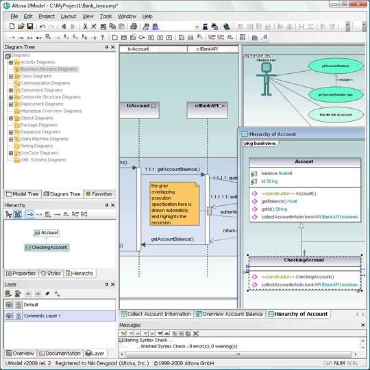 UModel offers advanced usability features that help lessen the UML learning curve, making modeling accessible to all project collaborators. With a focus on versatility in model design, UModel offers a completely customizable interface with color-coded elements to clearly indicate model characteristics.
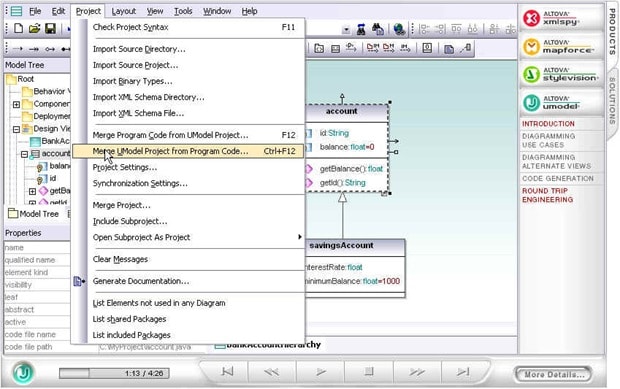
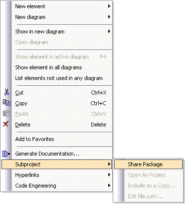
 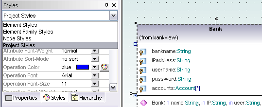 Users can also add additional customizations to enhance usability and communication that can be automatically applied to single elements, groups, or project-wide. UModel’s rich visual interface enables developers to quickly and easily sketch software designs to communicate all aspects of system architecture. This lightweight approach to UML design melds perfectly with the agile methodology, opening avenues for communication over dynamic project representations. UModel provides additional support for collaboration through support for shared packages, which enable developers to distribute their functional designs to other team members or import designs from other projects for reuse.
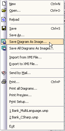
  Visual design representations can also easily be saved or printed as images for conceptual review by non-technical contributors.
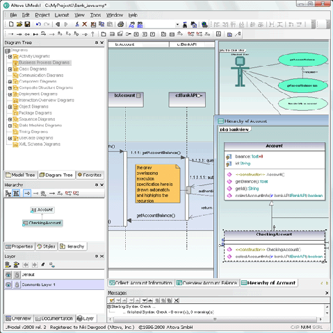
  Another compelling feature in UModel that drives inter-project communication as well as customer collaboration is the ease at which developers can create informative use case diagrams. UML use case diagrams tend to be a popular choice in agile modeling because they address one of the most challenging phases of the software development process, the visualization of user interaction. UModel use case diagram representations can be seamlessly illustrated with the help of advanced usability features and sophisticated graphical output.
 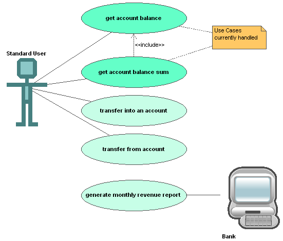 UModel also allows developers to auto-generate detailed documentation, including embedded images, in HTML, RTF, or Microsoft® Word. This feature addresses the second point of the Agile Manifesto, enabling teams to focus their efforts on software design, rather than getting buried in overbearing documentation that can sometimes stall project flow.
 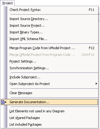 UModel’s robust round-trip engineering capabilities provide agile developers with the ability to quickly adapt and respond to change over the course of their project(s). UModel interprets modifications to project source code and synchronizes this with the corresponding UML diagram. UModel supports Java, C#, and Visual Basic, bringing advanced functionality and flexibility to the iterative development process.
  UModel also offers tight integration with the leading integrated development environments, Visual Studio® and Eclipse, giving developers the ability to seamlessly switch between the UML model and code editing windows and see any updates and changes reflected in real-time. UModel’s extensive usability and communication features offers development teams the ability to quickly change and adapt project requirements based on the results of incremental collaboration. Its graphical design interface and intuitive modeling capabilities enable team members to create compelling visual designs that can be easily interpreted by both technical and non-technical stakeholders at every stage of the project. Conclusion The wide acceptance of agile practices signifies a shift from the role-based, waterfall approach that was the norm just a few years ago. Businesses are recognizing that software projects are constantly changing and evolving at every step of the way. Development teams need to be able to manage change, to meet deadlines, and to lower costs. Nothing is quite as effective as the right set of concise diagrams to represent the essence of a software implementation. UML has the capacity to deliver structure to vague and abstract customer requirements, enabling developers to easily conceptualize the task at hand. With its flexible and advanced UML design interface, UModel is an ideal modeling tool for agile development, giving developers an inexpensive, easy-to-use, comprehensive modeling option with robust features for project collaboration and communication. UModel gives users the opportunity to capitalize on the extensive capabilities of the UML standard, but also offers the plasticity required of agile implementations. You can try UModel for free in your next agile development project. This technical brief and other resources are available in the Altova Library.


")


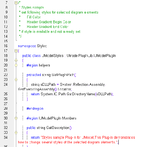
 The screen shot below shows UModel with several custom plug-ins installed. PlugInMenu3 adds the prefix m_ to the name whenever a new property is created in a class.
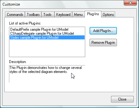
 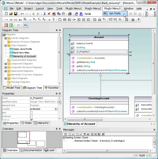 Note the plug-in custom toolbars directly above the Diagram Tree. The custom toolbar at the far left lets the user choose red or green to fill all currently-selected diagram elements. The Set Prefix toolbar lets the user turn the prefix feature on or off. If you want to try out the sample plug-ins yourself you can compile the sample code and add the resulting .dll files in the UModel Customize dialog. If you want to deploy the plug-ins across multiple workstations by sharing the .dll files, you will also have to register them manually at each workstation.
 We are interested to hear about the applications users devise for the UModel API, plug-ins, and custom stereotypes over the coming weeks. You can add a comment to this blog entry, exchange tips with other users in the


 In
In