Tag Archive for: UML tool

UML Modeling for C++ with UModel


C++ is one of the most powerful and efficient programming languages available, the de facto choice for high-performance computing, server applications, and complex architectures that demand the most powerful language constructs. The Unified Modeling Language™ (UML®) is the standard to design, visualize, and document models of software systems implemented in C++ and other source code languages.

Altova UModel competes with even the most advanced UML modeling tools with complete code engineering support in UML modeling for C++. UModel includes: C++ code generation from UML diagrams, reverse engineering C++ code to generate UML models, and round-trip engineering to update revisions to either C++ code and UML models.

Model transformation even lets developers convert an existing UML model designed for Java, C#, or Visual Basic to support C++.

Read more…

Tags: , , , ,

Software Modeling for Projects of Any Size


UModel is Altova’s tool for software modeling with support for all 14 UML diagrams, additional UML-style diagrams for databases and XML Schemas, plus Business Process Modeling (BPM), and SysML. UModel 2016 Release 2 adds code engineering support for C# 6.0, complementing support for Java, Visual Basic, and earlier versions of C#. Creating a UML model from existing code can be a great way to analyze and document an unfamiliar project.

BLOG_State_machine02

Read more…

Tags: , , , ,

Model Driven Architecture with Altova UModel


For Version 2012, UModel introduces Model Driven Architecture (MDA), with platform-independent models and a Model Transformation feature that transforms all code relevant modeling elements to and from UML, C#, Visual Basic, Java, databases, and XML Schema. Model Transformation A Model Driven Architecture approach to software engineering with platform independent models provides two primary advantages:

  • During the design phase, developers do not need to be concerned with the details and variations between software languages
  • An existing UModel project can be transformed from one source code language to another. For instance, a UML model for a C# application can become a Java or Visual Basic project

Users can even apply model transformation to projects that were reverse engineered from existing source code. For instance, an existing Java application can be reverse-engineered by UModel then transformed to generate Visual Basic classes, and many other possibilities are available. Model Transformation dialog in Altova UModel Platform Independent Models Model Driven Architecture is a set of standards and methods for applying the UML (Unified Modeling Language) administered by the Object Management Group. In Model Driven Architecture, the UML model of a software project is a platform independent model (PIM) that can be fully described without concern for the details of any specific programming language. This development strategy allows software architects and other developers to focus exclusively on logic required by the subject domain, rather than characteristics of any programming language. Data Type Mapping During model transformation, UModel maps data types from the source to the target to accommodate differences between languages. The Type Mapping dialog lets you review or even edit type mapping pairs. Type mapping for UML model transformation UModel also automatically adds the target language profile to the transformed project. UML Class Diagrams As part of the model transformation, UModel creates new UML classes and class diagrams for the target, reflecting classes and class diagrams in the original project. The screen shot below shows the Hierarchy of Account diagram for Visual Basic after model transformation from Java. The new Account class in the new folder named VB Target in the model tree contains Visual Basic syntax for all properties and operations. For instance, the new balance property is defined as the Visual Basic Single data type, whereas in Java the data type was float. After transformation, the original Account class for Java is preserved in the model in its original location in the model tree. The original UML design for Java will now generate code in multiple source code languages – Java and Visual Basic. UModel class diagram and Model Tree Persistent Transformation Parameters The transformation paradigm extends to updating existing transformations and merging the updates into the specified target models. Transformation parameters are stored in a Model Transformation Profile in the model. The Transformation Profile can be set to run transformations automatically before forward engineering code generation, and/or after reverse engineering, to update elements for one target language based on changes to model elements for another. UModel transformation parameters stored with model These Transformation Profile settings can also be changed at any time. UModel Transformation Profile settings This functionality lets UModel automate much of the maintenance of multiple source code languages as your cross-platform model evolves. If you’d like to try out Model Driven Architecture and model transformation with UModel 2012, you can download a free 30-day trial.

Tags: , , ,

UML Class Diagrams in Altova UModel


Altova products have long been recognized for their rich, intuitive user interface. One example is the UModel diagram window, which includes multiple display options for class diagrams to facilitate ease of use and improve information clarity in objected-oriented models. Class diagram style for projects that generate .NET (C# and Visual Basic) application code UModel 2011 Release 3 includes a new option for displaying class diagrams for .NET programmers. If your project will generate source code in .NET programming languages (C# or Visual Basic), your classes may contain .NET properties that can be called from outside like attributes, but are implemented internally as methods. To better organize .NET classes, UModel offers an option to display .NET properties and methods in separate operations compartments inside classes. UML class diagram for .NET This view is an optional setting in the Styles helper window for class diagram display and editing. Choosing to display separate .NET properties compartments or a single traditional UML operations compartment has no influence on code generated from the class.

View or Hide Class Properties and Operations Developers can collapse Properties and Operations compartments using convenient grab handle tools along the right edge. They can also customize the display of classes to show or hide individual class properties and operations. The right-click context menu offers a Visible Elements dialog for any selected class. UML class diagram showing properties and operations

Altova UModel visible elements dialog

This feature lets users simplify the diagram to focus on the properties and operations relevant to the task at hand. Hidden items are indicated by ellipses. UML class diagram with some properties and operations hidden Clicking on an ellipsis re-opens the Visible elements dialog. Options for Interface Notation UModel 2011 supports alternate diagram styles for interfaces between classes. By default, new interfaces are created in class diagram style with arrowhead styles and notations to indicate the interface creator and interface users. In the class diagram below, the developer wants to concentrate on class relationships and interfaces, so all the properties and operations compartments are collapsed. UML class diagram showing interfaces Interfaces have a special Toggle Notation quick-editing button to switch from the class diagram style to the UML ball and socket interface notation. UML class diagram toggle notation helper UML class diagram with alternate interface notation Visibility Icons vs. Mathematical Operators The UModel visibility icons, along with the visibility pull-down menus in the drawing window and properties menu, have been praised because they avoid confusion with common mathematical operators that can also appear in definitions of properties and operations. But users who prefer the traditional view can choose UML Style in the Project Styles helper window. Altova UModel Styles window and traditional visibility notation All the style settings selected to display class diagrams on screen are also applied when rendering project documentation in Word, RTF, or .html formats Find out for yourself how you can improve development of your object-oriented application by customizing the display of class diagrams with Altova UModel – download a free 30-day trial today!

Tags: , , , , , , ,

Solution to the Software Testing with State Machines Challenge


Last month in our blog on Software Testing for State Machines with Altova UModel we discovered unexpected behavior in our model of an air conditioning system and challenged readers to improve the design. This post describes one possible solution. When we ran the Tester application for our model, we saw that the Power switch did not turn the system off when it was in the Standby state. In the state machine diagram in our original model, the only route into Standby from Operating mode is via the Standby button, and the only way out of the Standby state is to press the Standby button again, as seen in the detail below. Detail of a state machine diagram in Altova UModel We can create an alternate exit to power off the system from the Standby state simply by drawing a new transition line from Standby to the Off state, and assigning powerButton() as the event that triggers the transition. UModel makes assigning the trigger easy by providing a pop-up window listing events that are already defined in the model. Pop-up list of triggers for transitions in a state machine diagram in Altova UModel Our completed revision to the model with the new transition from Standby to Off looks like this: State machine diagram in Altova UModel After regenerating the Java code and compiling the new version, we can run the Tester application again. The Debug output message window shows that the system entered Standby in Event 3. Event 4, activation of the Power button, now sets the state to Off. State machine test application generated by Altova UModel Find out for yourself how you can enhance the logic of your own state machine diagrams with Altova UModel – download a free 30-day trial today!

Tags: , , , , , ,

Software Testing for State Machines


Many varieties of software testing have gained prominence as developers search for ways to improve quality and meet project deadlines – code review, unit testing, regression testing, beta testing, test-driven development, and more. Regardless of a project’s goals or the source code language employed, it’s well accepted that the earlier a defect is found, the easier, cheaper, and more rapidly it can be fixed. Code generation from UML state machine diagrams, a new feature introduced in Altova UModel 2011 Release 2, can be used to validate conceptual logic very early in project development. Real-world design in a state machine diagram An example included with UModel provides a simple and realistic state machine diagram with a small test application you can run to see for yourself how easily it can be to test the logic of a design. The state machine diagram in the AirCondition.ump project in the UModel 2011 examples folder describes the operation of a typical heating and air conditioning system. State machine diagram in Altova UModel The system includes a power button shown on the left side in the transition from the Off state, a modeSelect function that selects heating or cooling, a speedSelect function for the fan, and a standby button that puts the system in the standby mode shown on the right. The example project folder includes all the code generated for the diagram by UModel in Java, C#, and Visual Basic. To try out the Java version, all we have to do is use the command javac STMTester.java to compile the code and java STMTester to run it. The tester application displays a simulated control panel with information windows about the heating and air conditioning unit. The operating buttons appear along the top, the current state is described in the first window, and output messages generated by changes in the system appear in the second window. Test control panel for state machine code generated by Altova UModel As shown above, the system initializes in the Off state, the mode is set to heater, and the fan is off. Before you operate the system, you might want to resize the control panel and state machine diagram to follow the actions of the tester application in the diagram itself, as shown in the reduced size image below. UModel state machine diagram and test control panel for generated code Operating the state machine When we click the powerButton, the Current state window is updated and a detailed description of the operations that occurred are listed as Event 1 in the Debug output messages window. Test control panel for state machine code generated by Altova UModel If it’s a hot day, we might want to change the mode to Cooling and increase the fan speed, which we can do by clicking the modeSelect and speedSelect buttons. The Current state window updates with each click, and Event 2 and Event 3 are added to the output messages window. Test control panel for state machine code generated by Altova UModel Now we can see how the tester application lets us fully exercise the logic of our state machine diagram by clicking every possible sequence of button selections to see if they produce the expected results. For instance if we put the unit in Standby mode (Event 4 below), then press speedSelect, we see in the output messages for Event 5 that no state change occurs in the substate named RegionSpeed. Compare Event 5 to Event 3 in the output messages window as shown below. Test control panel for state machine code generated by Altova UModel Now that the system is in Standby mode and we don’t need any heating or cooling, let’s save energy by pressing the Power button to turn it off. Test control panel for state machine code generated by Altova UModel Wait a second – it looks like nothing happened. No transition took place in Event 6, and the Current state in the top window is still Standby! Looking back at the state machine diagram, we can see the only way out of Standby mode is to press the Standby button again. Is that really the behavior an average user would expect, that the Power button would not turn off the system from Standby mode? Portion of a state machine diagram created with Altova UModel Just imagine how expensive this issue could be to fix if it was first identified much later in product development when the prototype was being tested by a regulatory agency! Here’s a challenge we’ll throw out on the table for our readers: how would you design another more direct route from the Standby state to the Off state? Testing your own state machines You can use the UModel state machine code generation example projects as templates to create test applications for your own designs. You will want to take advantage of the UModel feature that automatically creates operations in a class as you add operation names to transitions in your state machine. Altova UModel toolbar button for automatic creation of operations in classes Also, the UModel Help system includes detailed information about code generation from state machine diagrams and also uses the AirCondition.ump project file as an example. Find out for yourself how you can improve project development by testing the logic of your own state machine diagrams with Altova UModel – download a free 30-day trial today!

Tags: , , , , , ,

UML Database Modeling in UModel 2011


As software applications interact with growing amounts of data, database designs and structures become critical to development of successful projects. UModel® 2011, just launched on September 8, 2010, adds a new feature that empowers users to extend software modeling functionality by modeling relational databases along with Java, C#, and Visual Basic software applications. UModel 2011 accelerates database modeling with features that permits users to:

  • Import existing tables from all popular relational databases to create UML database diagrams
  • Modify diagrams for existing tables and generate SQL database change scripts to synchronize the database
  • Design new database tables and relationships from scratch and issue SQL CREATE scripts

UML database diagram UModel Database Diagram Supported Databases The UModel 2011 database diagram functionality supports multiple databases and automatically adjusts SQL dialects, data types, and other specialized features for the following databases:

  • Microsoft® SQL Server® 2000, 2005, 2008
  • IBM DB2® 8, 9
  • IBM DB2 for iSeries® v5.4, 6.1
  • Oracle® 9i, 10g, 11g
  • Sybase® 12
  • MySQL® 4, 5
  • PostgreSQL 8
  • Microsoft Access™ 2003, 2007

UModel Database Diagram Elements UModel 2011 database diagrams support all the following database elements:

  • Database schemas
  • Tables
  • Views
  • Check Constraints
  • Primary / Foreign / Unique keys
  • Indexes
  • Stored procedures
  • Functions
  • Triggers
  • Database Relationship Associations
  • Database Relationship with Attributes

Import Existing Database Structures Users can import an existing relational database via a selection in the UModel 2011 Project menu. UModel Project menu The Import SQL Database option opens the UModel 2011 Database Connection dialog, with the Database Connection Wizard and all the additional connection options available in DatabaseSpy and other Altova MissionKit tools that interact with popular relational databases. UModel database connection dialog When importing a database, UModel 2011 also automatically adds a database profile to the project. UModel 2011 database diagrams are displayed in a special category in the Diagram Tree Helper window. UModel Diagram Tree helper window Modifying Databases in the Model UModel 2011 database diagrams use a dedicated toolbar with icons indicating database elements that are shared with DatabaseSpy, easing the learning curve between tools. UModel database diagram toolbar As editing proceeds in UModel 2011, the SQL Auto-completion helper window assists with creation of diagrams valid for the SQL database type. UModel database diagram SQL autocompletion window As an alternative to working directly in the diagram, users can also edit database elements in the Properties helper window. UModel database diagram Properties helper window Database Change Scripts When a developer synchronizes program code from the UModel project, changes in any database diagram generate a Database Change Script with SQL commands to implement the revisions. Database Change Scripts created in UModel can be saved as SQL files, executed directly in the database, or opened in a DatabaseSpy SQL Editor window via a convenient button in the UModel Database Change Script dialog. UModel Database Change Script Conversely, if another team member modifies a table directly in the database, a developer can update the UML model by merging the database changes. UModel Message window After synchronization of the UML model with the latest version of the database, the database diagram shows a new column in the Teachers table. UModel updated database diagram Like all other UModel diagram types, UModel 2011 lets users save database diagrams as image files and include them in automatically-generated project documentation. Visit the Altova What’s New page to learn more about all the new features in the Altova MissionKit 2011. Model databases along with system requirements, business rules, and application code for your next development project – click here to download a free 30-day trial of UModel 2011 today!

Tags: , , , , , ,

Ride the UML Heat Wave


Ride the UML Heat Wave Get the Most Advanced UML Features – And Save 50%, 70%, or Even 90% Over Competing Tools! For a limited time we’re offering special savings on Altova UModel. Combining a rich visual interface with superior usability features, UModel also includes high-end code engineering functionality to empower you with the maximum benefits of UML software development. Starting at just $149, Altova UModel delivers the most advanced UML modeling features in the industry – at a fraction of the cost of other UML tools.
The same powerful functionality and ease of use that you’ve experienced in other Altova tools is packed into an affordable, intuitive UML modeling tool. UModel supports: Save 20% for a limited time * All 14 UML 2.3 diagrams * SysML and BPMN * Code gen and reverse engineering of Java, C#, and VB .NET * Round-trip engineering * XMI import / export * Visual Studio and Eclipse integration * 32- and 64-bit versions * And much more Altova UModel Cool off with an additional 20% discount
Enter code JULY10 during checkout in the Altova Online Shop for 20% off UModel. Act fast – this sizzling offer expires July 31, 2010. *Savings calculated by comparing published single-user prices of Sparx Enterprise Architect Engineering Edition, Magicdraw Professional Edition, and IBM Rational Software Architect Standard Edition including Rational Modeling Extension for Microsoft .NET, with equivalent UModel Enterprise Edition configured with comparable bundled software maintenance plans.

Tags: , ,

Splitting Large UML Sequence Diagrams


A new feature introduced in UModel 2010 release 2 allows you to split large sequence diagrams when you reverse engineer existing Java, C#, or Visual Basic source code. What are the advantages of splitting a sequence diagram, and how should you decide to split or not? Obviously, a single diagram makes it easy to examine in one view all the interactions that occur during the execution of a class operation. On the other hand, a large, complex diagram can be cumbersome to view, navigate, analyze, and print in a readable format. Fortunately, UModel 2010r2 makes it quick and easy to experiment. After you generate your sequence diagram, if you don’t like the results, just click the Undo button and you can create a new variation by choosing different options in the Sequence Diagram Generation dialog. Or, you can even apply the Generate Sequence Diagram feature more than once to the same class operation, and maintain multiple versions of the sequence diagram in your model. For instance, if you plan to modify the existing code, you might want to keep a permanent record of the “before” and “after” editions to document your changes. We recently adapted our analysis of a bank ATM legacy application to create two new Technical Briefs in the Reference Library section of the Altova Web site, titled Analyze a Legacy Application with Altova UModel and Enhance a Legacy Application with Altova UModel. Enhancement of the code included adding a new method called getFinalOkay directly in the original source code file for the Withdrawal class. When we completed the round trip by synchronizing our UModel project with the application code, the split version of the sequence diagram included a dedicated sub-diagram for the new method. The sub-diagram is automatically labeled with a note and hyperlinked to the main diagram. UML_sequence_diagram If you’re ready to see for yourself how a visual software model can help you work with your own legacy application, click here to download a fully-functional free trial of Altova UModel!

Tags: , , , , , ,

Part 5 – Analyzing a Legacy Application with Altova UModel


Previously in Part 1, Part 2, Part 3, and Part 4 of this series we applied Altova UModel reverse-engineering functionality to create UML diagrams for an ATM banking simulation application. After analyzing the existing architecture, we planned and implemented a new feature, the withdrawal fee. Even in a reduced size, our updated sequence diagram for the withdrawal transaction clearly represents in graphical form the nested logic structure of the source code. UML sequence diagram (reduced size) This morning we happened to run into the ATM product manager at the coffee machine. “You’ve been working on that ATM code for over a month now,” he said. “When am I going to see what you’ve accomplished?” We can take advantage of the UModel Generate Documentation feature to satisfy this request. UModel will automatically create customized documentation for our project in HTML, Microsoft Word, or RTF formats. The Include tab in the Generate Documentation dialog box lets us choose which diagram types to include, and to specify the level of detail for our report by allowing us to expand each diagram element type. Altova UModel Generate Documentation dialog box For an overview report, we can select all diagram types. We’ll also select class from the Elements list to show further information about the classes in our application. UModel helpfully asks if we want to add elements derived from class as well. Altova UModel Generate Documentation helper After we have selected or adjusted other document parameters, including fonts and sizes, UModel generates the report in just a few seconds. At the top of the first page, the report begins with an index of diagrams and a separate index of elements. Each indexed item is hyperlinked to a bookmark in the document. Altova UModel project documentation in Word format Regardless which format you choose, the resulting report is fully editable. For instance, we can add a footer that includes page numbers and a tag line recording the document creation date. We can grab the tag line UModel created to create our footer. Altova UModel project documentation tag line Our completed report contains all the UML diagrams that describe the legacy ATM application, with detailed class diagrams that show the class properties and operations. Additionally, the illustration of each class is accompanied by a hierarchy diagram to show the class relationships, and a list of all the class associations. Later on as our project evolves further, we can easily generate an updated version of the report. We could even take advantage of the UModel command line functionality or the UModel API to automate creation of project documentation, or we could attach the .html version of the report to our developer team wiki. But for now all we have to do is email the report to the ATM product manager. Conclusion We hope you’ve enjoyed following along with this exercise in Analyzing a Legacy Application with Altova UModel. Although we are ending the series here, in the real world there is much more work to do on our ATM application. For instance, the feature to permit users to accept the fee or cancel a withdrawal remains to be implemented. Or, we could update the legacy code with newer Java language constructs such as generics, annotations, and enumerations. If you’re already experienced with UML we hope we’ve shown you a new trick or two. If you are a developer who’s never tried UML, we wanted to give you some of the flavor and benefits of visual software modeling. Either way, if you’re ready to go further on your own project, click here to download a fully-functional free trial of Altova UModel.

Tags: , , , , , , , , ,

Part 4 – Analyzing a Legacy Application with Altova UModel


In Part 1 of this series we imported source code into Altova UModel to create a UML project and we examined a class diagram of our legacy ATM application. In Part 2 we created a series of UML use case diagrams to describe user interactions with the system and we planned an application enhancement to implement a withdrawal fee. In Part 3 we designed a UML state machine diagram to further analyze and document the operation of our system. In this installment we will return to our planned enhancement. We’ve been assigned to implement an ATM withdrawal fee of $2 for withdrawals less than $100 and $4 for withdrawals of $100 or more. In Part 2 we drew a use case diagram to show how users will interact with the new feature: UML use case diagram From our original analysis of the object-oriented classes in Part 1, we know our system contains a Withdrawal class, which is the logical place to implement our new feature. We can display a new class diagram for the Withdrawal class by selecting it in the Model Tree and choosing from the right-click context menu to create a new diagram. UModel Model Tree helper window UML class diagram We chose to create a hierarchy diagram so all the properties of the Withdrawal class are visible, including inherited properties from the Transaction class. Before implementing the fee feature, we have a related leftover question to investigate. We wanted to verify that the current code includes a test to make sure a withdrawal amount requested by the user does not exceed the current account balance. A UML sequence diagram will let us trace the execution flow of a withdrawal. UModel can automatically generate sequence diagrams from the operations of reverse-engineered classes. We can select the execute operation in our class diagram and choose Generate Sequence Diagram from the UModel right-click context menu to create the diagram we need. Altova UModel Sequence Diagram Generation dialog The UModel Sequence Diagram Generation dialog offers several options that will assist with our implementation of the new feature. We selected Automatically update because we will want to update the diagram later after we modify the code, and showing the code in a separate layer can help us focus on the withdrawal logic. UML sequence diagram The size of the scroll handles indicates we are only seeing a small portion of the sequence diagram in the current window. We can shrink the view to fit the window, but the text will probably be illegible. Instead, let’s take advantage the flexible UModel user interface to auto-hide the Diagram tree and Properties windows, which allows us to enlarge the Overview helper window: UModel Overview navigation window We can explore the sequence diagram by dragging the red square in the Overview window. This lets us quickly locate the comparison of the withdrawal amount and account balance. UML sequence diagram We can also see the error messages that display if the ATM does not contain enough cash or if the account balance is too low. UML sequence diagram Returning to the Withdrawal class diagram, we can add the fee property and set its default value: UML class diagram We’ll make a first pass through implementation of the fee logic without including the user cancel option. Updating the source code from our model adds the fee property to the Withdrawal class. Then we’ll jump into our favorite source code editor to implement the fee logic directly in the Withdrawal.java file. Testing our recompiled application shows the following: ATM Simulation The starting balance was $147. After withdrawing $100, the new balance is $43. The fee is displayed in a new message, and the ending balance is correct. But now the sequence diagram in our UML model is inaccurate because it doesn’t include the fee feature. We can correct the sequence diagram by updating the UML project from the revised source code. The UModel Messages window indicates that changes in the Withdrawal.java file caused the sequence diagram to be regenerated. And, we can easily navigate the diagram to locate our new test of the withdrawal amount to see if the fee needs to be increased to $4. image10a Now that our modified sequence diagram graphically represents updated operation of the ATM, we can be assured the harried driver we met in Part 3 of this series has enough cash to buy that ice cream cone! In our next installment we’ll take advantage of another UModel feature to generate rich project documentation for our work so far – one more advantage of keeping our UML model and application source code synchronized. If you’re ready to try Altova UModel on your own Java, C#, or Visual Basic legacy application, click here to download a free fully functional 30-day trial.

Tags: , , , , , , , ,

Part 3 – Analyzing a Legacy Application with Altova UModel


In Part 1 of this series we applied the reverse engineering functionality of Altova UModel to import source code from an existing ATM simulation application. We created a UML class diagram to illustrate the application’s class hierarchy and class relationships. In Part 2 we drew a UML use case diagram to document user interactions with the system and we drew several additional use case diagrams to document interaction details and a planned enhancement. In this installment we’ll look at the ATM from another point of view. On a hot summer afternoon, a harried driver spots an ice cream stand with a drive through lane up ahead. Just one problem – no cash! So he turns in at the strip mall parking lot and parks by an ATM in a glass kiosk. Before he even gets out of the car, our overheated bank customer wonders about the state of the ATM. Is another customer with complicated banking business already using it? Even if no one is inside kiosk, could the ATM be out of service? A UML state machine diagram (also called a state diagram) will let us map the states of our simulated ATM and the triggers, events, and transitions between states so we can better understand how our legacy application operates. Let’s return again to our experience running the simulation to get started: ATM Simulation Log In menu ATM Simulation Transaction Menu When we launched the legacy application, our simulated ATM entered its idle state, awaiting the first customer: UML State Machine Diagram start Next, it can be helpful to identify and draw additional states in disconnected ovals. We’ll be able to move these ovals around like pieces of a puzzle to find the logical sequence without worrying about the transitions from one state to the next. UML state machine diagram - preliminary This preliminary list of the ATM states is only our first rough draft. The state descriptions were suggested by our legacy application’s menu entries, and it’s obvious we can simplify: · There is no difference between Selecting First Transaction and Selecting Next Transaction, so these should be combined · Logging Out is probably not a state, but an instantaneous transition when our user presses 4 at the Transaction menu · We can assign user entry of a withdrawal amount or a deposit amount as sub-states within the Performing Transaction state The third item simplifies our diagram and would also be consistent with our treatment of user entry of the account number and PIN as part of Authenticating User. After we make these changes and add transitions, our diagram looks like this: UML state amachine diagram with transitions The simple transitions we’ve added are triggers that cause the ATM to leave one state and enter the next. Also, notice every state has at least one entry and one exit – otherwise the legacy application could force our user into a dead end. The diamond element between Selecting Transaction and Performing Transaction is the UML symbol for a choice of flows. At first it may seem illogical for the application to allow the user to sign out before performing any transaction, but that is an option our legacy application offers in the Transaction menu. And users in the real world have been known to change their minds at the last minute! We were careful to use consistent language wherever possible for our element names and descriptions. The states are named with verbs in the present tense that end in -ing. Transitions are labeled to indicate completion of the action that causes the state to change. Consistent element naming enhances diagram clarity. Once we have a working overview state diagram like the one above, it’s worthwhile to consider what happens if a transition is attempted, but not completed successfully. The ATM user might enter an invalid account number/PIN combination, or an authenticated user could request a withdrawal amount that exceeds the account balance. We can enhance our state diagram to include these possibilities: Complete UML state machine diagram Now our state machine diagram shows many alternate paths through the application execution, not just the single, all-successful “Happy Path.” We chose a vertical orientation for the layout of our diagram, but there is no rule dictating that form. Some applications will lend themselves to a horizontal layout, or maybe that is simply your personal preference. This illustration shows a small portion of our state machine diagram in horizontal form: UML state machine diagram in horizontal layout Whichever state machine diagram layout you choose, you should not draw transition lines that intersect or overlap. Drawing a UML state machine diagram may seem like overkill for our ATM simulation, since the legacy application is small, and we are all familiar with the way ATMs work. However, these techniques can be very illuminating when you have to work on a much larger application operating in an unfamiliar or complex subject domain. If you are ready to create UML state machine diagrams for your own Java, C#, or Visual Basic legacy application, click here to download a free fully functional 30-day trial of Altova UModel. In our next installment we’ll look in detail at the withdrawal transaction and the new feature we planned in Part 2.

Tags: , , , , , , , ,

Part 2 – Analyzing a Legacy Application with Altova UModel


In Part 1 of the Analyzing a Legacy Application series we introduced our ATM simulation app, imported the Java source code into a UModel project, and refined a class diagram to see an overview of the application classes and their relationships. In this entry we will create use case diagrams to document the current functionality of our ATM app and we’ll add to one use case diagram to plan a future enhancement. As we saw in Part 1, when a user runs our ATM simulation, he is asked to log in with an account number and PIN, then is presented with a transaction menu that summarizes all available interactions with the application: ATM Simulation transaction menu With the Transaction menu as a guide, we can create an overview use case diagram that documents user interactions with the ATM simulation: ATM Simulation overview use case diagram If you are familiar with UML notation, the first thing you may have noticed is the actor in our diagram doesn’t look like the typical UML stick figure. UModel lets software modelers assign any Windows .bmp image file to represent an actor in a use case diagram. We used the Properties helper window to assign an image from the library provided with UModel. Altova UModel Properties Window A use case diagram is not the appropriate place to define application flow or object-oriented classes, but simply to document how a user (an actor in UML terminology) interacts with the system. We can create additional use case diagrams to show more detail about each interaction. Expanding each interaction in a separate diagram improves clarity by keeping each layout simple and uncluttered and leaves plenty of space to try out different options. Detailed user sign in use case diagram We added authentication of the account number and PIN in a note instead of a use case oval because the ATM user is not the actor who performs that step. From real-life ATM experience we can guess (because we haven’t looked at the code yet) that a withdrawal will be cancelled if the amount requested is larger than the account balance. But comparing the withdrawal amount and account balance is not done by the user, so that activity is also not drawn in a use case oval. Withdraw cash use case diagram The arrow inside the Withdraw Cash use case indicates a hyperlink. UModel lets you can attach one or more hyperlinks to any element in your diagrams. A hyperlink can reference a URL, an external file, or another diagram. The hyperlink dialog even lets you define helper text for your hyperlinks. Altova UModel hyperlinks dialog Hyperlink pop-up text in use case diagram If you define more than one hyperlink, your helper text becomes a pop-up selection menu. Let’s say we’ve been assigned to modify the existing ATM Simulation to charge a fee for each withdrawal. If the withdrawal amount is less than $100, the fee will be $2. If the withdrawal amount is $100 or higher, the fee will be $4. Since the ATM is not stocked with one dollar bills, the fee must be charged against the account, not deducted from the cash withdrawal. The fee will be disclosed before any cash is dispensed and the user will be allowed to cancel the transaction. We can add the new requirement to our ATMWithdrawal use case diagram. Enhanced Withdraw Cash use case diagram We changed the color of the Approve fee use case oval to indicate this is a planned feature that is not yet implemented. Some developers would argue that the note attached to the Approve fee oval is redundant, since the include notation alone signifies that Approve fee is a required component of Withdraw Cash. But lots of people are confused about the difference between include and extend and it’s best to be absolutely clear. We can also take advantage of the UModel Layers feature to place all elements related to the new feature on a separate layer. Altova UModel Assign Layer context menu Now the Layers helper window allows us to show or hide the planned feature in our diagram view. Altova UModel Layer helper window Real world ATM experience tells us a transaction is missing from the legacy ATM simulation. The transaction menu does not offer an option to transfer funds between accounts. From the diagrams we’ve already created, we can see the original application design will make a transfer operation difficult to implement. The user sign in is based on the account number, and it appears that the legacy application does not understand the concept of a single bank customer who has both a checking account and a savings account. If our manager requests the transfer funds feature, we’ll need to have a conversation with our company’s enterprise software architect. A user ID linked to multiple accounts will need to be implemented not only in our ATM Simulation app, but also in the bank database. The Jolt award-winning Altova MissionKit for Enterprise Architects is a collection of eight XML, database, and UML tools for the enterprise software architect who may require UML modeling and database management tools in addition to advanced XML, Web services, and data integration capabilities. Click here to download a fully-functional 30-day trial. In the next installment we’ll look at the legacy ATM simulation from a completely different perspective as we prepare to dive into the code. See ya later!

Tags: , , , , , ,

Analyzing a Legacy Application with Altova UModel – Part 1


Sooner or later nearly every professional developer will be assigned to debug or add features to an existing application the developer did not help create. In these situations, inaccurate or incomplete documentation and lack of access to the original development team can pose huge obstacles. Fortunately, Altova UModel can reverse-engineer existing software to create a visual model that accelerates analysis and improves comprehension of a legacy application. This is the first of a series in posts where we will apply UModel, Altova’s UML tool for software modeling and development, to analyze an ATM (Automatic Teller Machine) simulation written in Java. The application is based on several ATM examples from popular Java tutorials. Since it is small and the operation of an ATM is familiar, we will focus more on techniques you can apply to your own Java, C#, and Visual Basic projects, rather than the example code. Here is a view of the legacy application running in a command window: Analyzing a Legacy Application with Altova UModel The original developer conveniently provided the sample account information, so we can log in. The application then presents a familiar ATM transaction menu: Analyzing a Legacy Application with Altova UModel If we inspect the folder containing the application, we see Java source files and compiled .class files, but no project files. Analyzing a Legacy Application with Altova UModel That’s not a problem. The UModel Project menu lets us import a project, a source directory, or even the binary files of a compiled application. Source code for very large projects is likely to be organized in multiple folders, so even when you have a project file, you may want to investigate one folder at a time. Altova UModel Project Menu Before we start, we’ll want to make sure to set the UModel Options to automatically draw any class associations defined in the source code: Altova UModel Options dialog As we import the folder, we’ll also want to include any JavaDocs comments in the source code as Documentation for our UModel project: Altova UModel Import Directory options For our first look at the legacy application we’ll want a high-level overview, so we won’t open all the optional compartments: Altova UModel diagram generation options UModel imports the project in just a few seconds, and the message window reports no errors. The Diagram Tree contains two diagrams: Altova UModel reverse engineering project We can click the Model Tree tab and expand the source folder to view icons representing all the Java classes UModel imported: image9 We can go back to the Diagram Tree to open the Content of source UML class diagram. After setting all the line styles to orthogonal and repositioning a few lines and classes to avoid overlap, we see the diagram clearly illustrates the application classes and their relationships: Altova UModel UML class diagram Note the name of the Transaction class is in italic, indicating it is an abstract class (or super class), and the BalanceInquiry, Withdrawal, and Deposit subclasses inherit its features. If you click the Transaction class to select it, inheritance is illustrated in the UModel Hierarchy helper window and any JavaDoc comments appearing in the source code immediately before the class definition are displayed in the Documentation window: Altova UModel Hierarchy window If we were using only a text editor to examine the legacy application, we would need to look into every single source code file to understand the hierarchy image shown above. That’s because the Transaction class does not internally identify its subclasses. When we do locate one subclass, it does not identify its siblings. And we can’t be sure some other illogically-named class is not a subclass of Transaction until we look at them all. You can also select each class individually to examine its documentation in the Documentation window. Or, if you prefer a cleaner diagram, you can remove the association labels from the diagram only: Altova UModel right-click context menu Now the asterisk representing the definition of “zero to many” multiplicity of Accounts in the BankDatabase is much more apparent. Altova UModel UML class diagram Another member of our development team found a partial class diagram purporting to represent the legacy project and passed it on. We can immediately see it does not look like the diagram UModel generated: UML class diagram for legacy application The documentation for our legacy app does not match the code – an unfortunate but common event! There are several differences between the old diagram and the one we generated:

· The associations between ATM and the physical components are shown as composition associations

· The association between ATM and the BankDatabase is described by a text annotation

· The association between ATM and Transaction also has a text annotation, and it does not even exist in the UModel diagram

· Multiplicity is defined at each end of each association, but none were created by UModel

Let’s consider each point:

· The representation of composition in the Java language is identical to ordinary association, so UModel could not deduce the composition characteristic. Of course the ATM “is composed of” a keypad, screen, cash dispenser, and deposit slot, so we can update the diagram to show composition.

· We can add a text annotation to any UModel association arrow. Simply click the arrow and start typing.

· If UModel did not create an association arrow between the ATM class and the Transaction, one must not be defined in the source code. We will postpone further investigation of this anomaly for now. · Multiplicity as shown in the legacy diagram would also require specific definition in the source code. We’ll leave this for investigation later too. Maybe that old diagram was left in the back of the file cabinet for a reason!

We’ll add the annotation, then update the aggregation characteristic of each ATM association in the UModel properties window. Let’s also use the UModel Layout toolbar to make the rectangles representing all the classes the same size. Now our class diagram looks like this: Modified UMLclass diagram for ATM project The completed class diagram just gets us started on our analysis. In the next installments we’ll drill deeper into the application code, automatically generate more UML diagrams, and draw some new diagrams of our own as our understanding of the existing code increases. If you want to jump in right away and reverse engineer your own Java, C#, or Visual Basic legacy app, click here to download a free, fully functional 30-day trial of Altova UModel.

Tags: , , , , , ,

New features in UModel 2009 UML modeling tool


The recently launched UModel 2009 includes new features that will help development teams of all sizes take maximum advantage of UML software modeling.

Support for version control systems

You can use version control to manage UModel project files and generated source code files. Over two dozen popular source code systems are supported. Check out the list here.

Extensive API to manipulate UModel or create UModel plug-ins

You could create an elaborate trace tool for testing and debugging that illustrates your application flow by manipulating elements in UModel diagrams, or you can create a simple plug-in that adds a custom command or menu option using your own icons and buttons. The UModel installation even includes plug-in code examples to help you get started. The sample plug-ins create new menu and toolbar options to provide shortcuts to particular style settings, to automate a series of tasks, and to reinforce a naming convention, all common modeling steps that are likely to be unique for each development team.
UModel plugin The sample code even shows you where to add the name and description description that appear in the UModel Customization dialog when a user installs your plug-in. UModel dialog 
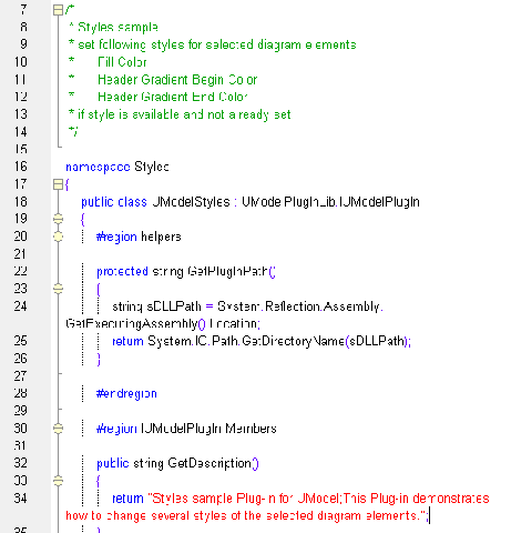
The screen shot below shows UModel with several custom plug-ins installed. PlugInMenu3 adds the prefix m_ to the name whenever a new property is created in a class. UModel UML tool 
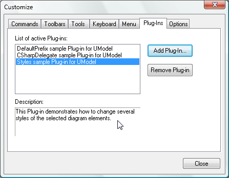
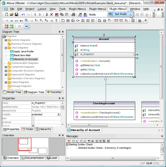
Note the plug-in custom toolbars directly above the Diagram Tree. The custom toolbar at the far left lets the user choose red or green to fill all currently-selected diagram elements. The Set Prefix toolbar lets the user turn the prefix feature on or off. If you want to try out the sample plug-ins yourself you can compile the sample code and add the resulting .dll files in the UModel Customize dialog. If you want to deploy the plug-ins across multiple workstations by sharing the .dll files, you will also have to register them manually at each workstation.

Support for profile diagrams in the latest UML 2.2 specification

An enterprise software architect might use custom stereotypes to define specific properties suitable to your team’s problem domain. The architect could then distribute these to the team via a shared package. The UModel Properties helper window lets you define custom stereotypes with a high level of precision. UModel UML profile diagram We are interested to hear about the applications users devise for the UModel API, plug-ins, and custom stereotypes over the coming weeks. You can add a comment to this blog entry, exchange tips with other users in the Altova Support Forum, or contact us through the link on the right side of the Altova Case Studies page to collaborate on a case study. If your development team hasn’t enjoyed the benefits of model-based software development, you can download a fully-functional free trial to test drive UModel 2009 for 30 days.

Tags: , , , ,