Part 3 – Analyzing a Legacy Application with Altova UModel
In Part 1 of this series we applied the reverse engineering functionality of Altova UModel to import source code from an existing ATM simulation application. We created a UML class diagram to illustrate the application’s class hierarchy and class relationships. In Part 2 we drew a UML use case diagram to document user interactions with the system and we drew several additional use case diagrams to document interaction details and a planned enhancement. In this installment we’ll look at the ATM from another point of view. On a hot summer afternoon, a harried driver spots an ice cream stand with a drive through lane up ahead. Just one problem – no cash! So he turns in at the strip mall parking lot and parks by an ATM in a glass kiosk. Before he even gets out of the car, our overheated bank customer wonders about the state of the ATM. Is another customer with complicated banking business already using it? Even if no one is inside kiosk, could the ATM be out of service? A UML state machine diagram (also called a state diagram) will let us map the states of our simulated ATM and the triggers, events, and transitions between states so we can better understand how our legacy application operates. Let’s return again to our experience running the simulation to get started: 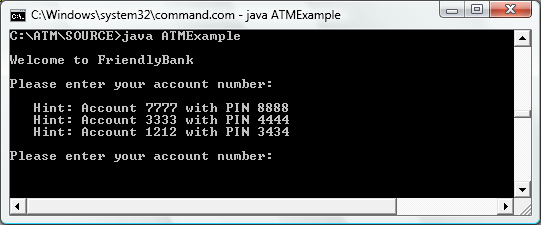
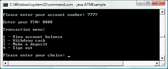 When we launched the legacy application, our simulated ATM entered its idle state, awaiting the first customer:
 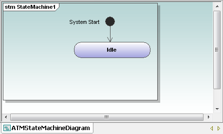 Next, it can be helpful to identify and draw additional states in disconnected ovals. We’ll be able to move these ovals around like pieces of a puzzle to find the logical sequence without worrying about the transitions from one state to the next.
 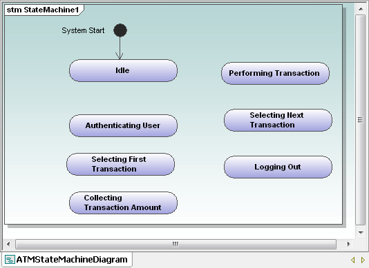 This preliminary list of the ATM states is only our first rough draft. The state descriptions were suggested by our legacy application’s menu entries, and it’s obvious we can simplify: · There is no difference between Selecting First Transaction and Selecting Next Transaction, so these should be combined · Logging Out is probably not a state, but an instantaneous transition when our user presses 4 at the Transaction menu · We can assign user entry of a withdrawal amount or a deposit amount as sub-states within the Performing Transaction state The third item simplifies our diagram and would also be consistent with our treatment of user entry of the account number and PIN as part of Authenticating User. After we make these changes and add transitions, our diagram looks like this:
 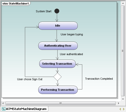 The simple transitions we’ve added are triggers that cause the ATM to leave one state and enter the next. Also, notice every state has at least one entry and one exit – otherwise the legacy application could force our user into a dead end. The diamond element between Selecting Transaction and Performing Transaction is the UML symbol for a choice of flows. At first it may seem illogical for the application to allow the user to sign out before performing any transaction, but that is an option our legacy application offers in the Transaction menu. And users in the real world have been known to change their minds at the last minute! We were careful to use consistent language wherever possible for our element names and descriptions. The states are named with verbs in the present tense that end in -ing. Transitions are labeled to indicate completion of the action that causes the state to change. Consistent element naming enhances diagram clarity. Once we have a working overview state diagram like the one above, it’s worthwhile to consider what happens if a transition is attempted, but not completed successfully. The ATM user might enter an invalid account number/PIN combination, or an authenticated user could request a withdrawal amount that exceeds the account balance. We can enhance our state diagram to include these possibilities:
 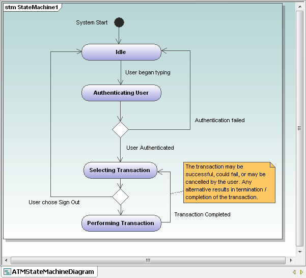 Now our state machine diagram shows many alternate paths through the application execution, not just the single, all-successful “Happy Path.” We chose a vertical orientation for the layout of our diagram, but there is no rule dictating that form. Some applications will lend themselves to a horizontal layout, or maybe that is simply your personal preference. This illustration shows a small portion of our state machine diagram in horizontal form:
 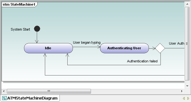 Whichever state machine diagram layout you choose, you should not draw transition lines that intersect or overlap. Drawing a UML state machine diagram may seem like overkill for our ATM simulation, since the legacy application is small, and we are all familiar with the way ATMs work. However, these techniques can be very illuminating when you have to work on a much larger application operating in an unfamiliar or complex subject domain. If you are ready to create UML state machine diagrams for your own Java, C#, or Visual Basic legacy application, click here to download a free fully functional 30-day trial of Altova UModel. In our next installment we’ll look in detail at the withdrawal transaction and the new feature we planned in Part 2.
