Expandable If-Else Works like a Switch Statement in MapForce


In response to several user requests, the if-else component in MapForce has been enhanced in MapForce 2011 Release 2 to accommodate any number of variables. This feature, which is equivalent to a switch statement in many programming languages, enables you to easily control the flow of data in a mapping project by matching a value to a selected criterion. For example, the screenshot below shows the if-then component used in combination with other components to analyze temperature data and produce the following results:

  • If temp is greater than 20, true is passed on to bool1 and "high" is passed on to value-true1.
  • If temp is less than 5, true is passed on to bool2 and "low" is passed on to value-true2.
  • Only one of the value-true parameters can be true for any given temperature, and that is the one that is passed on to the desc attribute in the target component.
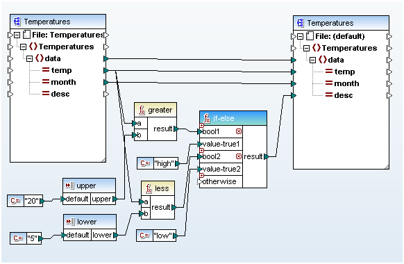
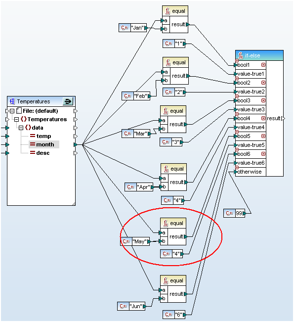
Expandable if-else example included with MapForce The screenshot above is taken from the sample file Classify Temperatures.mfd included during the MapForce installation, so you can immediately process the sample data or modify the mapping to see the output for yourself. The new expandable if-else functionality helps developers build data mappings more rapidly, creates a mapping diagram that displays the conditional test more effectively, and facilitates testing and debugging because the expanded if-else function is much easier to read than a cascading structure of individual components. This is even more obvious when you have to evaluate a large number of conditions. The screenshot below shows a conversion from string to number where the string consists of a three-letter abbreviation of the month. (To save space here, this if-else function only processes strings for the first six months of the year.) Expandable if-else statement in MapForce In a copy-paste oversight we forgot to update the output constant for May from the value 4 to 5. That’s a much easier error to find and fix when you can see all the logic in one view!(UPDATE: We originally created this example to illustrate the advantages of Expanded If-Else over nested or cascading If-Else mappings that can quickly grow too large to view on a single screen. For a better design for solving this and other similar conversions using a look-up table, see the Switch Statement vs. Look-up Table in MapForce blog post.) Find out for yourself how easy it is to use expanded if-else functions in your own data mapping projects. Download a free 30-day trial of MapForce.
Tags: , ,

Using the StyleVision Combo Box to Support Data Visibility Requirements


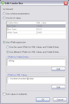
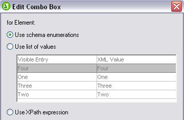
Altova is always on the lookout for ways to help software developers and architects meet the challenges presented by the increasingly complex collection, storage and retrieval requirements of end users. In fact, we recently enhanced the functionality of the combo box in StyleVision to provide developers with additional flexibility around collecting and populating data. There are three ways to define the items in a combo box and their associated XML values – automatically based on a valid schema, manually with a list of populated values and dynamically with an XPath expression. In the latter two scenarios, the value that appears to the end user can be different than the value that will populate the file or database. This feature is particularly useful in cases where the “meaning” of the underlying data isn’t obvious or intelligible to an end user (e.g., a seven digit part number). The values in a combo box can be automatically populated with enumerations from a valid schema. In this case the value that appears to the end user is identical to the XML value that will populate the file or database.Altova StyleVision The functionality is perfect in cases where the elements in the schema provide an accurate reflection of the data content as understood by multiple stakeholders (e.g., end user selects Four to indicate group assignment, which populates the file with the XML value Four). Developers can also populate the combo box manually, defining both the value that appears to the end user and the XML value that will populate the file or database. These values do not need to be the same. So, for example, an end user can select Acme Dishwasher, Stainless while a complex product code populates the file or database used to generate the purchase order. This is an especially useful for collecting standardized data using organization or department-specific taxonomies and supporting multi-lingual applications. Finally, combo boxes can be populated dynamically via XPath expression. Use the same XPath expression to define the values that the end user sees as well as their associated XML values or use different XPath expressions to identify discrete values. If you use different XPath expressions the values the end user sees and their XML values are automatically mapped to one another. In the example below, the end user is prompted to select the group to which he is currently assigned (one, two, three or four). However the group number (not the name) will populate the database. Please note that the values the end user sees could be sorted in alphabetical (or numerical) order if the Sort Values in Authentic box were to be checked. The XPath expressions above produce the output below – the end user selects “Two” but a numeric value is saved to the XML document. The combo box – particularly one that supports the differentiation of values visible to the end user and those that actually populate the database or file – is an invaluable resource in the design of electronic forms. StyleVision automatically generates the stylesheet for an electronic form along with those for HTML, PDF, Word 20007+ and RTF from your template. The Authentic eForm provides an interface for end users to enter and edit XML or database data and is viewable in Authentic View, Altova’s free graphical XML document editor. Have you used enhanced combo box functionality to solve a data entry or population issue? Share it with our active community of StyleVision users by posting to our Facebook wall, commenting here on our blog or joining a discussion in our User Forum on our Website!

Tags: , ,

Software Testing for State Machines


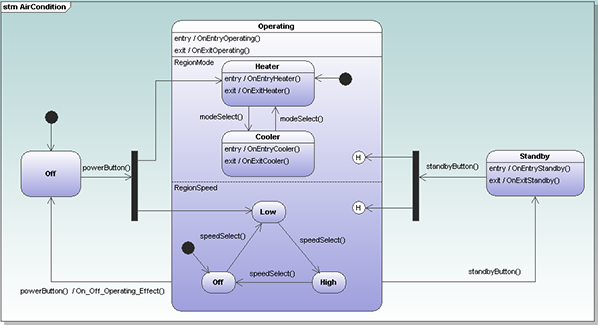
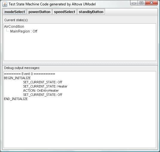
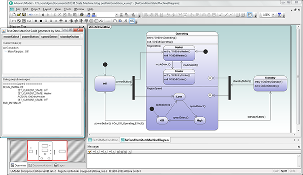
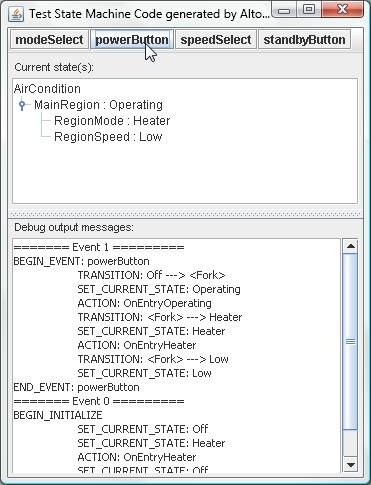
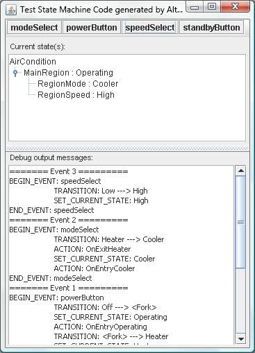
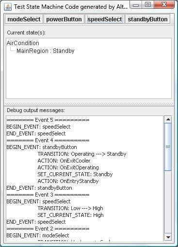
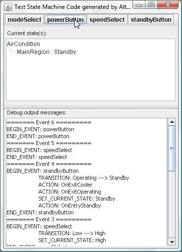
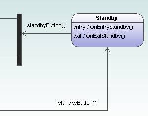
Many varieties of software testing have gained prominence as developers search for ways to improve quality and meet project deadlines – code review, unit testing, regression testing, beta testing, test-driven development, and more. Regardless of a project’s goals or the source code language employed, it’s well accepted that the earlier a defect is found, the easier, cheaper, and more rapidly it can be fixed. Code generation from UML state machine diagrams, a new feature introduced in Altova UModel 2011 Release 2, can be used to validate conceptual logic very early in project development. Real-world design in a state machine diagram An example included with UModel provides a simple and realistic state machine diagram with a small test application you can run to see for yourself how easily it can be to test the logic of a design. The state machine diagram in the AirCondition.ump project in the UModel 2011 examples folder describes the operation of a typical heating and air conditioning system. State machine diagram in Altova UModel The system includes a power button shown on the left side in the transition from the Off state, a modeSelect function that selects heating or cooling, a speedSelect function for the fan, and a standby button that puts the system in the standby mode shown on the right. The example project folder includes all the code generated for the diagram by UModel in Java, C#, and Visual Basic. To try out the Java version, all we have to do is use the command javac STMTester.java to compile the code and java STMTester to run it. The tester application displays a simulated control panel with information windows about the heating and air conditioning unit. The operating buttons appear along the top, the current state is described in the first window, and output messages generated by changes in the system appear in the second window. Test control panel for state machine code generated by Altova UModel As shown above, the system initializes in the Off state, the mode is set to heater, and the fan is off. Before you operate the system, you might want to resize the control panel and state machine diagram to follow the actions of the tester application in the diagram itself, as shown in the reduced size image below. UModel state machine diagram and test control panel for generated code Operating the state machine When we click the powerButton, the Current state window is updated and a detailed description of the operations that occurred are listed as Event 1 in the Debug output messages window. Test control panel for state machine code generated by Altova UModel If it’s a hot day, we might want to change the mode to Cooling and increase the fan speed, which we can do by clicking the modeSelect and speedSelect buttons. The Current state window updates with each click, and Event 2 and Event 3 are added to the output messages window. Test control panel for state machine code generated by Altova UModel Now we can see how the tester application lets us fully exercise the logic of our state machine diagram by clicking every possible sequence of button selections to see if they produce the expected results. For instance if we put the unit in Standby mode (Event 4 below), then press speedSelect, we see in the output messages for Event 5 that no state change occurs in the substate named RegionSpeed. Compare Event 5 to Event 3 in the output messages window as shown below. Test control panel for state machine code generated by Altova UModel Now that the system is in Standby mode and we don’t need any heating or cooling, let’s save energy by pressing the Power button to turn it off. Test control panel for state machine code generated by Altova UModel Wait a second – it looks like nothing happened. No transition took place in Event 6, and the Current state in the top window is still Standby! Looking back at the state machine diagram, we can see the only way out of Standby mode is to press the Standby button again. Is that really the behavior an average user would expect, that the Power button would not turn off the system from Standby mode? Portion of a state machine diagram created with Altova UModel Just imagine how expensive this issue could be to fix if it was first identified much later in product development when the prototype was being tested by a regulatory agency! Here’s a challenge we’ll throw out on the table for our readers: how would you design another more direct route from the Standby state to the Off state? Testing your own state machines You can use the UModel state machine code generation example projects as templates to create test applications for your own designs. You will want to take advantage of the UModel feature that automatically creates operations in a class as you add operation names to transitions in your state machine. Altova UModel toolbar button for automatic creation of operations in classes Also, the UModel Help system includes detailed information about code generation from state machine diagrams and also uses the AirCondition.ump project file as an example. Find out for yourself how you can improve project development by testing the logic of your own state machine diagrams with Altova UModel – download a free 30-day trial today!

Tags: , , , , , ,